Project SOLD
It has been over a year, and I have had yet another inquiry into the sale of the RV-10 project. My bad, should have closed things up a year ago.
The project was sold quickly, I had a couple of solid offers. A gentleman in Utah now owns the project and I wish him well. I retired, moved to Idaho, and a lot transpired the last year. Poor excuse.
Alas, I will leave this blog for a while if there is any interest. Good luck to all.
-Cliff
Sunday, August 26, 2018
I have not done much on the plane the last three months. My RA has become problematic again, and my meds are changing. Due to both the rheumatoid arthritis and the medications, my FAA medical is toast. I am hoping the new meds work, but even if they do, they are not allowed by the FAA. So it appears my flying days are over.
It is difficult to continue on with the plane project without any hope of being PIC (pilot in command) in the future. So I have decided to wind things up and sell the plane in the current state. Thanks for the support of everyone to date. I will try and keep everyone informed of the transition and sale of my RV-10 project. No worries, I have finally become comfortable with relinquishing this phase of my life. I have LOVED building the plane, but all good things do come to an end. Time to pursue some other hobbies that don't require an FAA medical exam.
Here are the details for.......
RV-10 Project for Sale
I am Vans builder # 41620. My project started about 3 1/2 years ago. My progress to date:
Empennage 95% complete.
Fuselage 80% (Quickbuild, lacking gear, engine cowling, front windscreen)
Wings 90% (Quickbuild and in a rolling cart)


Interior is mostly painted with Sherwin Williams JetFlex Semi-gloss Blue-Black, which actually looks like a darker grey. (L09027) (See pictures in this blog for a good idea). Still have a lot of paint left over, and it has been refrigerated and still works well.
All bare aluminum parts prepped with scotch-brite, PreKote cleansed and then primed with AKZO primer. Some of Van’s parts got re-primed, but major parts of fuse and wings left with the wash primer. Although not as robust as AKZO, Van’s primer looked fine.
Overhead console has been customized a little bit with LED lights and mounting pads, and wood veneer (Amboyna burl, aka Narra). Plenty of extra veneer for instrument panel finishing. Again, see the blog photos.
I have plumbed the tunnel for EFI with return lines. EFII pumps and filters installed, although I was also considering SDS EFI. You can easily go any direction at this point, Ross at SDS indicated the EFII pumps and regulators would work fine with his system. All lines to date pressure tested, as well as brake lines pressure tested. You could even go with mechanical FI or carburetor, just cap off the return lines.
Have done some electrical, but only a little bit. I do have 4 runs of conduit run down each side from the front to the tailcone. Also conduit run along front windscreen pillars, and along each side of tailcone. Plenty of room for electrical runs and whatever electrical architecture you desire.
Independent overview has been done by local AP/IA who has consistently given positive feedback.
Will not sell off individual items for now, would like to sell the entire project. Any interested parties can email me directly at cliff@langloisdds.com.
These are the cost of my purchases through Vans:
Empennage 4,068
QB Wing & Fuselage 39,620
Finishing 13,331
Aftermarket items 12,275
Total 69,294
I am willing to take $50k for the entire project. I would like to sell the entire project at this point, would rather not consider parting out kits/items. I am in southern Cal, zip 91791. I have tried to be very conscientious throughout the build, and any interested parties are welcome to contact me with questions. I think my build blog (CliffsRV10.blogspot.com) is quite a comprehensive review of what I have done. Shipping, transport is up to the buyer.
I measured the fuselage and at this stage it is just shy of 19’. Uhaul has a 26’ truck with 23’ of useable area which should transport it just fine. Fuselage is attached to a welded steel base with 10” pneumatic wheels. I can roll it around easily by myself, and would be happy to help the buyer load things up.
Wings are on a rolling wooden cart that is about 12’6” x 2’6”. Very sturdy 2x6 construction with 5” castering wheels. I have not done any work to the wings except working on lighting install on the fiberglass wingtips.
The HS, VS, rudder and elevators are hanging up in my shop rafters where they have been safe.
Here is a partial list of the extras I have purchased: (I have forgotten quite a few, someone will benefit).
Control Approach pedals - $1200
Pacific Oil Cooler (8001649)- $650
Lamar starter solenoid - $100
Anti-Splat oil separator - $180
Stainless heater bypass valves - $225
Fuel injection pumps/regulator - $800
PlaneAround door locks (3 point) - $420
AeroSport Products:
310 Carbon panel w/vents - $1460
Throttle quadrant - $350
Low profile handle - $345
Overhead aerovents - $460
Center console - $775
Overhead console - $1100
Full set interior panels/vents - $995
NACA vent valve controller - $265
AeroLED taillight - $400
Baja Design lights - $200
FlyLED position/strobes - $250
CIES digital fuel senders (4) - $1400
Total extras: $12,275
5/6/2018
A couple of months have passed by since I updated my blog. Today was the day I dedicated to getting caught up. I hope everyone is doing well.....
.
I finally received my aftermarket rudder pedals. Extremely nice design, fit and finish. After a bit of massaging, they are in! Also got a chance at some new safety wiring I had not done before.


Then decided to add some firewall penetrations. These are stainless steel pass-throughs for electrical wiring. Lightweight, well built and reliable. I made some holes, dimpled, caulked with fire-resistant goo and riveted them in place.


 Stainless steel pull rivets did the job.
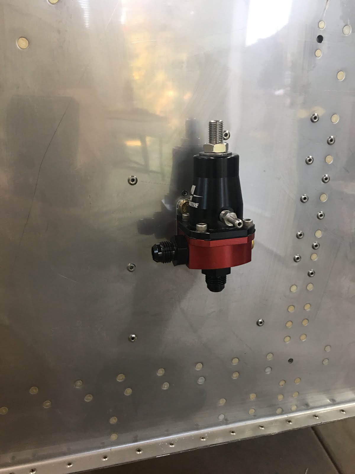
Then while I was at it on the firewall, I added a doubler and riveted on my air/oil separator. Made by a guy in Redlands, a nice unit.

Then made another doubler for the fuel pump pressure regulator. It greatly helped stiffen up the firewall and made for a secure connection.


Then I placed Heat Shield Mat on the bottom 2/3 of the firewall. Need to do some final riveting above before I finish up with it.
After all of that this is how the firewall and engine mount looks. Sweet!


Then I bolted on the starter relay. Also placed a diode across it to bleed off current spikes caused by the coil. This is kind of detailed and it took a day of reading up on it to get it all straight. But basically, it protects the switch from arcing when the relay shuts down. Read all about it online if you are a masochist.

And also decided to mount the oil cooler. Nice unit made in La Verne by Pacific Oil Cooler Service. A great outfit, and I got a factory tour when I went up there. Saw oil and radiator coolers for P-51's, P-38's and the like. It was really a great time, and I learned a lot.

Then I started crawling back into the tunnel again to run the rudder cables and a few more wiring runs. Now is when I appreciate the smooth edges, no sharp corners, and conduit previously placed.


I had to make some holes and place some guide bushings under the battery tray, where I forgot the rudder cables would go. No big deal, just another couple of hours gone!
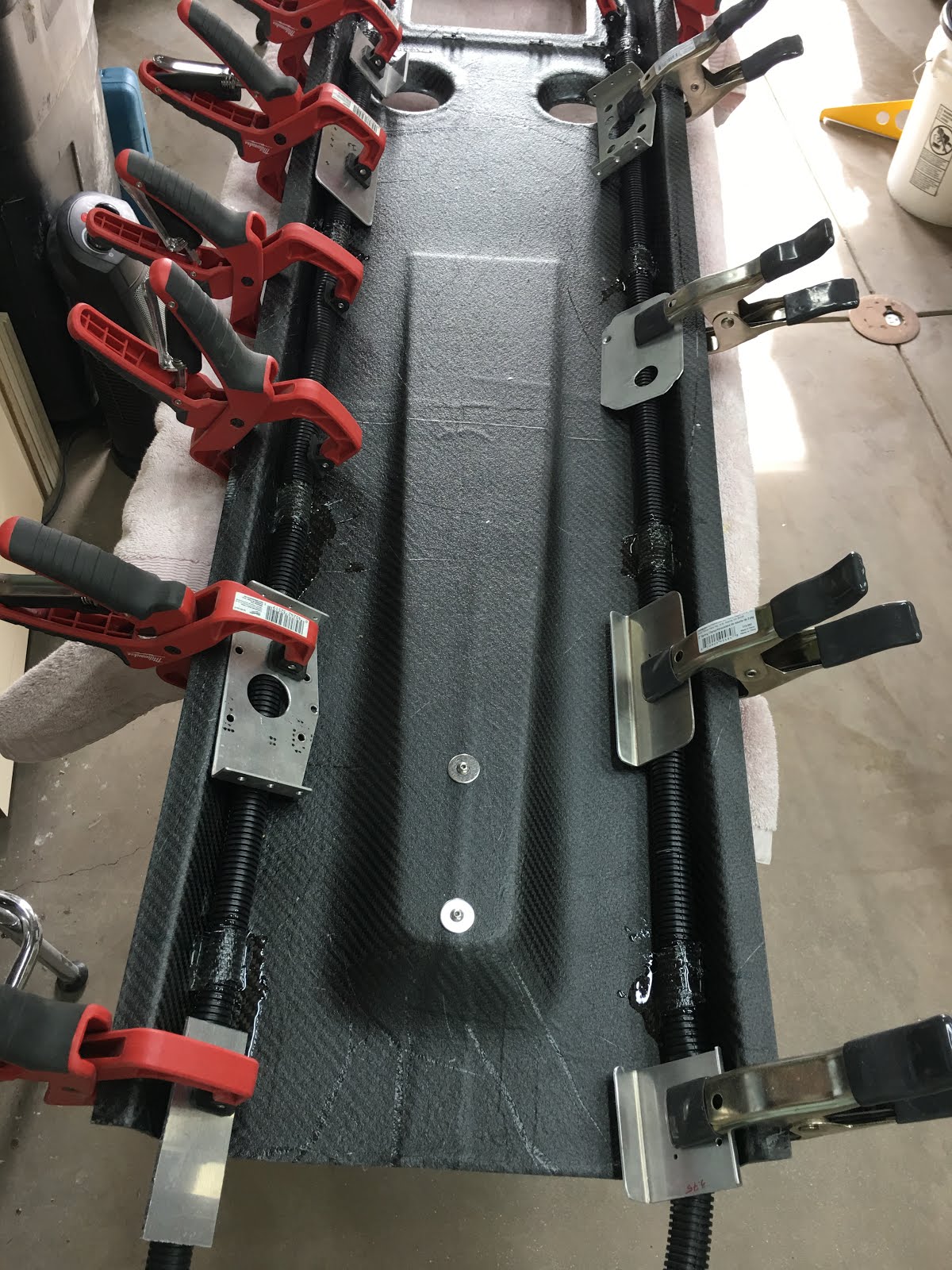
Forward in the tunnel, I wanted to finish up the fuel pump assembly before final fit of the rudder pedal arms. I decided I wanted the entire fuel pump assembly to be easily removed (4 screws). The biggest hurdle was coming up with a rock solid electrical connection. If this fails, I would be a rock in the air. I decided to use Anderson Power Pole connectors, which are really great connectors. I made a small bracket which screws onto the side of the fuel pump assembly. The electrical connector has a pin which keeps it locked, as well as the bracket/clamp which keeps it solid. I am confident.


And here is the finished fuel pump assembly on the bench. Everything looks snug, and labeled so tomorrow I won't forget what's what.
 And here is the assembly mounted in the tunnel. Everything fit, which is amazing.

And then I finished up the last return fuel line, and added the wiring bundle for the fuel pumps. It was a lot of work making sure things were secure, safe and out of the way.
And this was the week we let Gerard pass into the hereafter. He was a constant companion, and by far the best dog we have ever lived with. Just to make matters really fun, I had a root canal procedure in the morning, and said good-bye to Gerard in the afternoon. What a day.


So as I was wiring up the fuel pumps, I ended up with a coil of wires, waiting for switches and an electrical bus. Not wanting to forget what end was what, I popped for a thermal printer that prints onto heat shrink tubing. What a great idea and product.

Here is what they look like after heated onto the wiring. Very durable, and guaranteed not to fall off. I
like it.

So after the fuel pump wiring, decided to finish up the tunnel. Ran the heater hoses, the front one was a snap. The back not. With the new rudder pedal arms, and the fuel return line, it is not a welcome item in the tunnel. So I made the decision to reduce it to 1" through part of the tunnel. Worked well, and I am have seen a lot of builders do similar.
A couple views of the tunnel, showing heater hose routing.


And finally, the tunnel cover fit into place. Placed another joint in it for ease of removal.

Started running my ground wire from the back battery tray to the front common ground point. I intend on a "star" ground configuration, with one single common ground on the firewall. Hopefully no ground-loops and a solid system.

Gave myself a number of grounding tabs on both sides of the firewall. I wanted a nice husky brass bolt 5/16" for the pass through attachment. After having trouble locating one, I went down to the Aviation Depot, and got a toilet bolt. Nice.
Decided to turn my attention to the top forward fuselage skin. One issue I had was that the hand-holds on the glare shield (dash) were impinging on my new fancy carbon fiber instrument panel. I decided to move them further out for more room.


Above you can see how they were spaced on the left, and how I moved a new set out further to the edge. I plan on a padded roll on the edge anway, which will make the grip size about just right. You can also see in these above pics the 2" holes in the glare shield that I punched out for defrost fans.

Yours truly in action punching out the holes with my pnuematic hole punch. It sure makes nice smooth holes with ease. Not that tricky with aluminum, but still, it is a great tool.

Had a free day, so I bucked up and crawled back into the tailcone to finish up my pitot-static system lines. The standard equipment from Van's already fell off when I bumped it. So I bought some nice hardware and re-did the lines back to the tailcone. It went quickly, well, and is much more secure.
Then back to the defrost fans. I drilled, dimpled, and screwed them into place after a coat of black spray. I will cover with a dash cover, but figured why not.
Then I fabbed up a small circuit board and disconnects for the fans. If (when) anything needs to be replaced, it will make life a lot easier.


Seemed like a good time to add my ground tabs to the sub-panel. These are mounted on ABS plastic, so that they are isolated grounds. Each will connect to the main firewall (toilet bolt) ground, so all grounds are centralized without any chance for ground loops.


The above shows one of the ground tabs. front and back. The ground bolt easily clears the aluminum, assuring grounding only through a future ground wire. I have one on each side for high and low current items, hopefully further avoiding any interference.

This was also about the time a patient and good friend of mine, Greg Goodson, stopped by to look at the project. He is a PhD physics guy, and just retired from JPL where he built spacecraft. It was fun to have him look at critique the build. Greg is a great guy and I appreciate his friendship.
And finally received my flexible SS brake lines, after they were sent back and shortened. Really, the guy was great. Took a few inches off here and there and didn't charge me anything extra. Very great service.


Installed all the lines and they fit much better. Pressure tested and all looks good!
My fiberglass wingtips have been knocking around waiting to be finished, so I figured it was time. I have them now fit for mounting the landing, taxi, strobe and position lights. It is all kind of a custom arrangement. Not sure what inspired me or cursed me as the case may be.


Now I have a lot of fiberglass pretty work to do. It goes a little slow as I put on fiberglass and epoxy, and then need to wait until the next day. But it is easy enough, and any mistake can be corrected.
 In the meantime I started work on a vacuum system to make the clear lenses for the taxi lights. Van's provides the tip lenses for the landing light area, but the taxi lights were my own design.
So before I cut into them, I made fiberglass molds of the tips so I would have the shape.
Then I poured positive casts of the tips in stone (dental stone to be specific). Primed and painted them up.
Then I tore apart an old toaster oven and made a heating chamber, and built a vacuum platform alongside it.


I heated up some .060" PETG clear plastic, which is similar to water bottle plastic. Very flexible, durable and tough. This is what Van's other lenses are made of, so I figured what the heck. 4 Minutes of heat, about 2" of sag, and a shop vac stuck into my vacuum table.


 It was quite uneventful, and successful. My only bugaboo was that the hot PTEG stuck to my acrylic spray painted surface. It messed up my model, but the lens was still good. Next run I will spray a release agent on it. The added trick is that I made the heater and vacuum table such that they would fit together like a box. So storage will be easier.
 The first lens sits on top of the vacuum unit, not a bad first run.
Okay, you are up to date! I hope everyone is healthy and doing well. I hope to finalize my electrical design in the next month, have been working on it for a year. Take care everyone!
************************************************************************
2/5/2018
It has been about 14 weeks since I last updated the blog. I have been very busy, just have not had time to give to the blog. But here goes.....
I last left off with just starting the doors. The amount of dust created from trimming the doors and door flanges was atrocious. I think I had the mother of all OSHA violations and the messiest shop in creation. It became imperative to move the fuselage off my "rotisserie" and onto a rolling cart. This way I can roll it outside the shop to do any future dusty fiberglass sanding/cutting.

So out came the welding unit, steel and Harbor Freight tires. I put straight 10" pneumatic tires on the front and the swivel dudes on the back so that I can steer it. The front supports aluminum stock that is inserted into the landing gear weldments. The back has a plywood support that I covered with a soft towel as it rests on the aluminum skin.

I now can move it out when I do dirty fiberglass jobs. Much cleaner and healthier. I can even do it by myself as the pneumatic tires roll over the door threshold quite easily, and onto the grass. I find the grass is a great place to make a lot of fiberglass dust.

One day I got bored and decided to make up some battery cables for the master solenoids and grounds. I have a really cool hydraulic crimping tool that does an excellent job on these welding cables. Some heat shrink with adhesive and voila. This is a bit disoriented, but it is the fuselage floor behind the baggage bulkhead.
Now back to the doors and windows. I have the doors initially hung and fit, so now time to put in the windows. Van's plans have you fiberglass and epoxy in the windows. Many have complained that it is difficult and time consuming. And if a window were to need replacing, you get to re-paint the plane.
So there is a guy on YouTube who installs acrylic windows in Glastars, and has done it for 25 years. He has a series of videos detailing his installation technique using GE Silpruf silicone to bond in the windows. It is a slick technique, and I decided to go his route.
My first window I was too scared to stop and take pictures, show I will show the method on the right rear window:

First the window is trimmed to just fit into the space. I held it in place with just a couple of clecos. Then run a line around the window spaced evenly 1/4" away from the canopy joggle.

I then use an angle grinder with a large abrasive disc on it to "trim" away up to the line. This works great, accurate and quick. With such a large disc there is very little worry about hopping over the edge and scarring the acrylic window.

Once I am satisfied with the fit, I mark the inside of the window as to where the window emerges from the inside lip of the window recess. This will be the inside tape line. At all times I am using a Vis-a-Vis wet erase pen. It works great, and is easy to remove. No risk of permanent window damage.

Then a large piece of blue painter's tape is run around short of the inside line. Followed by a small 1/4" line of masking tape is run right up to the line. Then the line is wiped clear.
There is even a second line of 1/4" tape run over the first. It does get confusing. And finally you flip it over and cover the outside to completely cover the edge with blue painter's tape. (The inside area to be siliconed is then sandpapered rough for better adhesion.)


Here are a bunch of little silicone stand-offs I cut up and glued with silicone to the fiberglass. That keeps the acrylic window spaced off the fiberglass evenly and allows for a uniform layer of silicone. Also the fuselage taped off to make clean up easier and quicker.
Stay with me!

A nice big bead of silicone is applied to the fiberglass flange. The GE Silpruf is nice, it is quite fluid when compressed, but not enough to run, so it stays where it gets put. Also comes in a lot of colors, obviously I chose black. It is also very UV resistant, which is great.

And the window is placed, with all the clecos popped in and tightened down just enough to make it flush with the fuselage. I then go around and remove as much of the silicone as I can using a flexible tool, commonly known as old credit cards.

Then I carefully work my way around removing any excess silicone, and peeling back the blue tape as I go. This results in a nice clean application, ready for a final fillet after painting. I also flip the small hardwood "bridges" under the clecos as I go, in case there is any residual silicone present.

And here is all the tape removed and I let everything cure for a week before removal of the clecos. Even without the edge sealed, I could not press these out with all the weight I could put on them. Secure. I will try and leave the tape and plastic film for protection as long as possible.
And now it is onto the doors. Van's has us put washers and locknuts on the door hinges. While these are secure, they are a PITA to put on and off. While fitting the doors, painting the plane and any future maintenance I could tell this was not going to be fun. So I worked a weekend or two changing both the fuselage side of the hinge and door side to nutplates, so that all I have to do is screw and unscrew the hinges for removal without having an assistant or cursing.
So on the left is Van's washer/locknut arrangement. On the right is my nutplate modification. The nutplates are very secure and don't require orangutan arms to install.


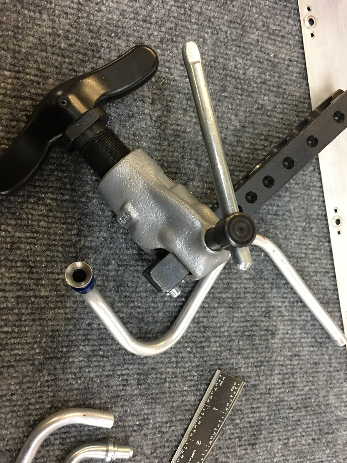
Next issue was the gas strut to open/close the door(s). Van's strut is notoriously weak, so the word on the street was to order a Bansebach gas strut. I did so, but found that the brackets would bind as the door opens and closes. Due to the curvatures of the door, things just don't open in a flat plane. So on opening/closing it would only go so far before binding.
This is how the initial hardware looked. It just didn't work well.

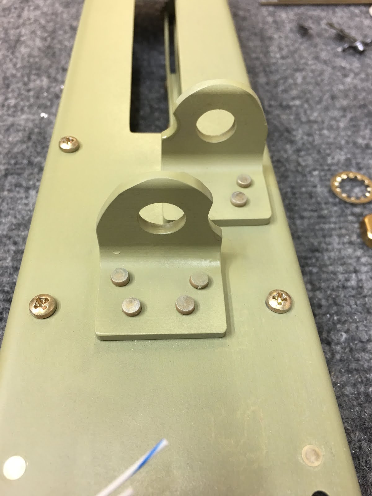
At the bottom and top of the original strut are "rigid" pivot attachments. You can see it above, and to the right you can see my new choice, a pivoting tie-rod end that can swivel. No problem as things move out of plane. I had a bracket I used for a template, but needed it a bit longer as the new swivel end was a bit larger in diameter. The red trace is original size, and blue trace is extended. I drilled the #12 hole first for the attachment bolt.

Onto the mill where I milled out a 1/2" wide slot for the swivel end. Milling aluminum is like cutting butter, quite fun.

This shows the smaller slot of the original bracket, which would not accomodate the larger swivel end. Also the newer slot cut into the bracket stock.

And now the swivel end in place, verifiying that the new slot will work with the larger end.

I rough cut the bracket out of the bar stock on the band saw, and then used the mill to flatten all the surfaces as close as I could.


After polishing up and repeating all the steps, I have two duplicates. I already started fitting the one, hence the mounting holes.

With the new swivel end mounted up in the bracket, I now have room to play and should not bind when the door opens and closes.


And finally I have the upper hinge replaced with a pivoting elbow, like most cars have on struts. It again allows for play and it opens and closes easily now. I reinforced the upper area with an aluminum plate just for assurance.

I just about have the doors all in now, will update this soon!
10/20/2017
I have been neglegent about keeping up the blog, will make amends! I have done a lot since August, so here goes.....
I last left off with the windows fit to the fuselage, but not installed. I need to wait until the doors are finish before final installation. My doors were delayed with my finish kit (the final installment from Vans), so I went to work elsewhere. Plenty to do.
The carbon fiber middle console and panel needed to be installed. So there was a lot of positioning, drilling and locating holes.


 Here is a picture of the fuel selector installed through the lower console. The installation looks great, although the drilling and measuring was time consuming to make sure I didn't make a mistake.
I also decided at this time to put another "split" into the tunnel cover. With the middle panel console in place, I will be unable to remove the tunnel cover. So I split it just ahead of the fuel selector. And yes, I missed the hole location a tiny bit. Not that it mattered.


Then I fit the throttle quadrant. This had to be positioned just so in order to fit the console. Refer to the last pictures.

And finally the middle console fits just right over the throttle quadrant, and the fuel selector lines right up with the bezel. Not rocket science, but everything had to fit just right.

And while I continued to wait for the finish kit, I went to work on the wingtip lights. There are a million options out there. I went for a simple position/strobe kit put together by another RV pilot in Australia. It was easy and fun to build, reasonably priced, and very robust. For the landing light I went with an off-road LED that is blindingly bright and very rugged. Decent price, just have to come up with a good custom mount for it.

Here are all the suspects on my bench waiting for the solder iron and mounting brackets.

And this is how I am going to mount the landing light/LEDs. I ran out of real estate to do what I wanted, so I did some modification of the wingtip fiberglass. Why can't I make things simple?
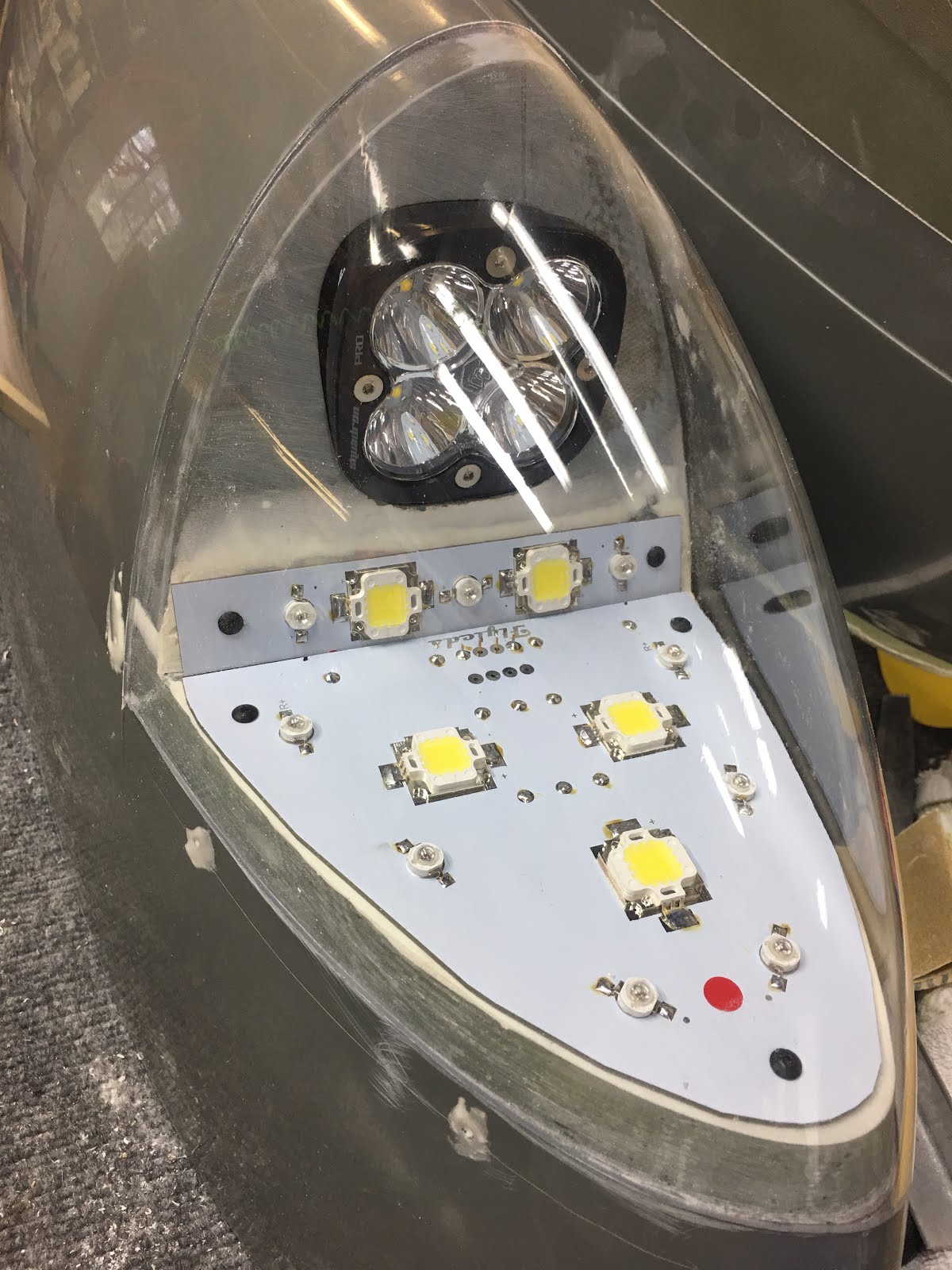
Here is the almost finished result. I had to move one side in to gain a little real estate, and then everything fit just fine. I am happy with the result.

The finish kit finally arrived! As usual it took longer than I had anticipated, but not that I didn't have things to do. My last big box from Van's.

Starting with the doors. Lots of work to do. First, bonding and two together with epoxy after some structural internal items. I had to rough trim these to shape, and did a trial run for the glue-up with epoxy. They cure with the shape of the cabin top, and hopefully when trimmed up will have the same profile, or close thereto.

The window areas were very easy to mark out with my little marking tool. I cannot live without this little dude.
There is an inner and outer shell, and inside I am putting two reinforcements.

The first reinforcement is for the gas strut attachment, and is standard in the plans. The aluminum plate is bonded with structural epoxy and riveted to boot. Makes the door very solid where gas lift will push up on the door.

The next reinforcement is for a pull strap, recommended by many other builders. I just bonded and riveted an aluminum piece with a platenut. Should be a good pull point.

So put them back on the canopy, this time with a lot of epoxy. Then pulled them off the next day and this is kind of what you see. I then trimmed both shells now as one, making sure they were a little wider than needed.

And then did a LOT of careful sanding to get the door to just fit inside the opening for a flush fit. After the hinges and locks are installed I will do final fit and finish.
Now we are up to date. I will try and stay on it!
***********************************************************************
8/13/2017
I last left off with the overhead console almost finished. My veneer application totally failed on the access panels, and I needed to re-work them. After a LOT more experimentation, this is the final process I ended up with, and it works great.

I found that covering the back side of the aluminum and the top of the veneer with painters tape made cleanup much easier. No need to get loads of epoxy where not needed, as it is tough stuff. Both pieces here are ready for epoxy.
The veneer was already fairly rough, it did not need sanding. The aluminum needed to be scuffed with 80 grit for good retention.


And the additional wrinkle that worked great, using Julie's vacuum sealer in the kitchen. Of course your work has to fit the vacuum bags, but in this case I was lucky. I sealed the veneer/epoxy/aluminum sandwich in the bag and when the vacuum is pulled, all the excess epoxy squishes out the side. and the veneer becomes impregnated with epoxy, making it very stable. It is then easier to do some touch up sanding.
 I then sprayed it with a 2k clear urethane spray. This stuff is a 2-part spray, there is a red cap that is put onto the bottom of the can. Once it is activated, it is good for about 2 days. It is a catalyzed urethane, very tough and it flashes off and cures rapidly. A nice thick finish can be built up quickly. I was able to cover my pieces without too much effort and was very pleased with the way the finish flows out and then cures rapidly. The biggest drawback is that this has isocyanates, very nasty stuff. Precautions and respiratory equipment mandatory.
Above shows the gloss I can achieve with this finish, and the three panels that I finished and am fairly happy with.

 And finally the panel, all wired up and with the vents in place. The final wiring of the smallest panel will wait. I plan on putting a bank of switches that will be for taxi/landing/nav/strobes and cabin lights. I think I have it all spaced out adequately, will see in the near future. I also put some diodes in the circuit so that each light can be turned on individually, or all on or off together. This will give the individual control, but the pilot can turn it all off as needed. I temporarily powered it all up and everything worked as planned.
And finally the day came for mating the cabin top to the fuselage for good. I scuffed the mating aluminum surfaces around the door opening. They door opening is attached with both bolts and structural epoxy (epoxy with flox/cotton fibers). I did a couple test fits until everything fit well, and then mixed up a lot of epoxy.

The above shows the canopy just before I swung it over for the last time and bolted/epoxied into place. A pretty big moment!
One of the challenges was running some flexible conduit through the rear bulkhead. I had to oversize the holes a bit in order to get the conduit through when lowering the canopy. So to strengthen and seal the conduit holes I made doublers that I riveted and glued to the bulkhead. In the pictures below the small brown wire is temporary power to the overhead console.


The orange hose is lightweight riser conduit for networking cable. It is fire rated, yet is fairly lightweight. Rigid until it is heated with a heat gun, then can be shaped and molded. When it cools down it retains it's new shape. It was fairly easy work to shape it for the intake air that goes to the valve and then into the overhead console. This makes the overhead console charged with air, giving good airflow to the overhead vents when opened. When it is really cold the valve can be closed, keeping any cold air from entering the overhead console.
 I once again used 3M 2216 epoxy, very similar to Proseal. But a big advantage is that in the gun, I can deliver just what I want to use, there is no mixing, and I can apply with the mixing tip. When done I just toss the disposale tip and re-cap. When it sets it seems bulletproof. Very strong and slightly flexible.
I then received my carbon fiber panel and lower console. Very nice, lightweight aftermarket parts produced by Aerosports Products. (same as the overhead console). Since I couldn't wait, I temporarily installed the panel and consoles and turned on the overhead lights. It was very satisfying! The fake instruments are Garmin stick-ons for planning purposes.

Now, back to work. I have been working on the side with Stein Air in Minnesota regarding my electrical system. I have gotten far enough along that I figured I would mount my electrical contactors by the battery tray. I won't go through the entire process, as the pics pretty much tell the story. As for the three contactors, one for each battery and a third is a cross-tie in case one buss loses power. When my electrical drawing is finished I will post it.


Mounted back in the plane, I made up a few cables just for fun. I used #4 welding wire, it is flexible, beefy and works very well. Received a hydraulic crimper a year or so ago, and it does an excellent job of crimping. Add some adhesive lined heat shrink and it makes a great custom cable.

The next step on the plans is to trim and fit the windows. Installation will be done later, but I guess it is easier at this step. The acrylic windows are rough cut, and to cut them to within 1/4" I used an angle grinder and cut-off wheel. No problem. But getting close to a trim line is scary with a cut-off wheel. So I purchased a new (sorely needed) electric grinder, with a phenolic adapter for sanding discs. The PSA (pressure sensitive adhesive) discs I bought are 80 grit, and with the large 6" disc I can trim the acrylic easily, with no fear of jumping up over the edge and scarring the window.


I trimmed both rear windows easily and set them aside for later. The front windscreen I trimmed the same, and it took me a long morning to have it ready to go. It was a bit bulkier and thicker, but still the grinder made taking off material a snap. I will need to take a tiny bit more down for an even border around each windw, but for now it's fine. These will not be set in place until after the doors are finished.

The doors are ordered, but Vans is slow. I am supposed to receive them end of Sept/beginning of Oct. In the meanwhile I have a lot to do, finishing up a lot of items and even have interior panels if I get bored.
******************************************************
6/12/2017
It has been a couple of months now, and it is time that I updated the blog. Have been busy, but progress has slowed down as some of the work is just plain slow and tedious.
I have been continually working on the overhead console. The rear end of it had a 3/4" flange that went up against the bulkhead wall. It was bulky and made fitting things difficult. So I decided to cut it off and fiberglass it right up against the bulkhead without a flange. I will bond a couple of tabs on the inside to hold it snug, and use ProSeal or similar sealant/adhesive to seal it up. I feel much better about that route.
Here is the overhead console in place, after I buttered it up with flox/epoxy mixture. I attached some boards covered with cellophane tape to keep the epoxy mixture from flowing down. After it cured, it was removed easily and you can easily see where I added. I filled the cleco holes, added some micro/epoxy mixture for a smooth surface and finished it out.


I looked back at my log, and I think I have spent 3 months on the blasted overhead console. It has been a lot of epoxy/fiberglass/finish work. But in the end it is work it, I think.
So after all the fiberglass, epoxy, micro filler, polyester filler and so on, I was finally happy with everything and ready to proceed. There were a LOT of pinholes in the surface, which is typical with fiberglass and resin layups. The first thing to do is skim coat on a layer of plain epoxy to fill the holes. You can see the shiny surface on the right picture.....


This seals up most of the pinholes, but there were still a few pesky ones around. Then one more round of sanding with 220 until all looked good for paint.


I did a lot of paint research, ended up with Sherwin Williams JetFlex paint. It is a polyurethane catalyzed paint. Not cheap stuff! But I mixed it according to their reps recommendation, and I was really pleased with how it sprayed.......


This last view is with the inspection panels in place. I veneered them with amboya burl wood. I used 3M 77 spray adhesive, a fairly universal spray adhesive. Not soon after the veneer bubbled all over, apparently the finish softened the adhesive. Dang. So now I have to re-do them. No big deal, just more time spent doing things over.
Inspired by my success painting the overhead console, I next tackled the fuselage interior. I spent almost a full day and a full roll of the wide 3M painting tape. What a great tape!


And after a morning of spraying away..........


Again, very happy with the paint, nice result for an amateur.

And of late I have been working on installing the LED cabin lights and map lights, along with all the switches. Kind of a spaghetti of wires, after all switches and lights installed I will wrap them up and make it all pretty and clean.
Lastly, I decided to re-plumb the fuel filter in the tunnel. My previous version was with a filter that could not be cleaned, but could only be replaced. I decided to go with a more robust filter, and made it easier to remove by mounting it on top of the fuel pumps. I had a flexible fuel line made that goes from the fuel selector to the filter, so it can be removed easily for maintenance. I still need to put a supporting clamp on the rigid line.

Getting close to riveting the canopy onto the fuselage for the final time. That will be a big occasion and I will make sure and update at that point!
******************************************************************************
4/10/2017
Lots of progress!
It has been almost 6 weeks, time for an update. I had made a mount for the fuel pump, and decided that it was horrible. Too many parts and weird. So I trashed it and started from scratch....
I first made some 1/8" aluminum angles that I attached with existing holes for the floor pans and tunnel sides.


Then fabricated a couple of .063" aluminum plate to bridge the space, and match drilled them into the angles.

And then on top of the plates, laid out the fuel pump assembly with the pre-filter. I had to drop the pre-filter plate about 1/8" to keep the pre-filter exactly in line with the fitting. It all lines up good, however, I am not wild about the pre-filter as it is disposable. I am ordering a new pre-filter that has a cleansable screen.

So then I (once again) deburred, polished and scuffed all the parts. I also prepped parts for the elevator trim mechanism and overhead ram air fittings. I try to save up so spraying a small amount makes more sense.
And finally, all the nutplates were riveted in place and the mount riveted in place. The fuel filter module is mounted along with the pre-filter. Nice, everything is secure and fits.

Overhead ram air inlets......
I am installing the overhead console, that will be the source of overhead air vents. The console will receive it's air flow from the rear, so I need to put a couple of 2" holes in the bulkhead, as well as a couple 3/4" holes for conduit. Up to 3/4" holes are easy with the step-drill, but the big holes are more of a challenge (especially when I get to the SS firewall). So for Christmas my folks gifted me a pneumatic hole punch. Very cool tool that really makes short work of accurate holes.

So I traced with a sharpie the lower border of the overhead console. Marked the positions for the holes, and enlarged to 3/4".

Space is a little tight here, had to make sure the supports and nutplates were clear.

And here is the pneumatic punch at work. I already punched the first hole, and am working on the second one. Very clean hole, and very easy. No excitement which is good.

Here is a view from the back side. This is the cutting die that is threaded onto a 3/4" rod. It pulls through without any effort.
The two holes enable me to mount a couple of 2" flanges to attach the air ducting to. The air can be completely shut off in cold weather by an electronic servo, which is the blue anodized apparatus. Each passenger will have their own overhead vent, but this gives ability to completely shut off the air if desired.


So the parts were prepped and primed, then riveted in with some 3M 2216, which is similar to Proseal. Very tough epoxy. This stiffened back up the bulkhead nicely after I punched a bunch of holes in it.

From the front you can see the flush rivets, and the additional 3/4" holes for conduits.

And finally some of the ducting placed from the bulkhead flanges to the servo controller. I am using PVC electrical riser conduit because it is very light, rigid and can be gently heated and then molded into position. Once it cools it is very strong, kind of fun to work with.
One of the above pics shows a bunch of parts for the elevator trim mechanism. Here are pictures of it going together.......


The electrical servo pushes/pulls the bellcrank which pivots in the mount. Washers provided for the bellcrank were tight, and had to be sanded down and polished to enable a nice fit.
The cables which attach to the bellcrank deflected off the mounting brackets. This was all made according to the standard plans, so I don't know what Van's is thinking. But no big deal, I notched the brackets, polished and primed them. Now the cables lie straight and all is good. This will now sit on the shelf until I put wheels on the plane.

Also was able to fabricate and mount a position sensor for my flaps. Surprisingly this is not a standard item on an RV-10. Everyone seems to roll their own version, but most everyone uses a POS-12 sensor from Ray Allen. I more or less copied another builders version.
Here is just a simple L-shaped aluminum bracket for the sensor, attached to the tunnel wall. Also made a small bracket for the flap tube. Between the two some type of armature is needed to link them up. Best suggestions were radio controlled model parts. They actually are very nice quality, these are nylon and SS ball joints with a titanium turnbuckle arm. The big trick is to get it placed just right.


The sensor is basically just a 5 ohm-5k ohm resistor. As the arm is retracted or extended the resistance changes. This value can be fed to an electronic display or LED light. I will wire it into the Garmin electronic display. The first and last 10% of travel are not reliable, so the goal is to get full rotation of the flap tube with the right amount of arm travel.

Here I have the lower/up limit set to 7.2 ohms. So many factors come into play it is challenging. But for the lower end that works.
 And here it is set to 4.95 kohms, at he lower/down position. I ran it back and forth enough to satisfy myself that it is fairly accurate and repeatable.
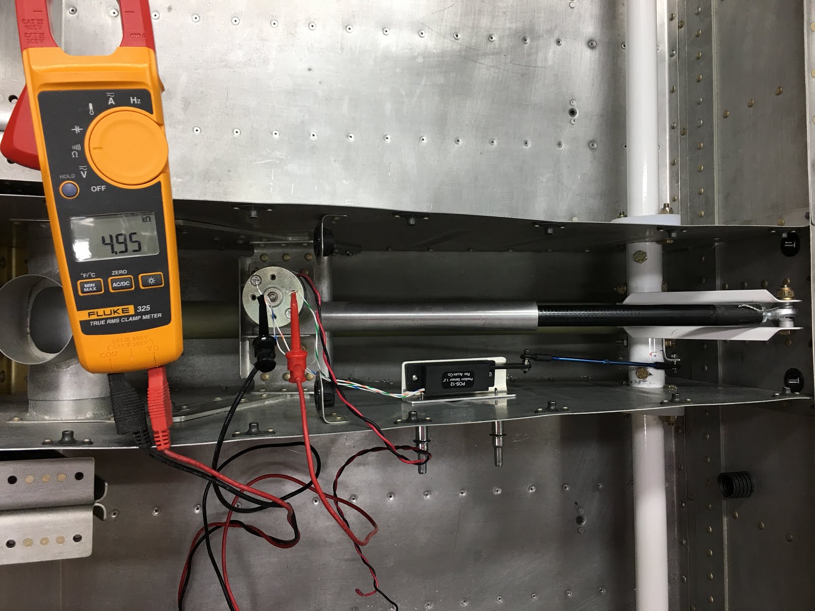
Hopefully it will work fine once I integrate it with the electronics one day. Once again, removed, primed, and finally installed for good. (I hope).
Now back to the cabin top and overhead console. Before I proceeded with gluing the console to the top, I epoxied in some more conduit along the bottom of the console. I can envision a few circuits running back along the console, but having extra conduit is not a bad thing.

And before gluing in the console, I used some epoxy/flox mixture to glue in some conduit inside the front canopy supports. There is a natural cavity there, and rather than just fill it over it seems like a natural spot for conduit.

I notched the console where needed, and tacked down the conduit every 6-8". It will be covered with a couple layers of fiberglass in a bit.
So I broke out the 3M 2216 epoxy, and squirted onto the canopy and console, then slapped them together with clecos. It was sure a nice mixing system, love the gun and mixing tips.


This is the fiberglass extension I made for the console, since I needed it a bit longer to hide the conduit, etc.

I glassed over the conduits and bonded in the extension of the console. Sorry, lost a few pics. Then used some Rage filler (like Bondo) to fill over and smooth everything out.

Then I placed a few strips of fiberglass to fair in the edges of the canopy for a seamless fit. The fabric you so to the left is dacron, used as "peel-ply". Once the resin sets, it is peeled off, resulting in a fractured surface that is easy to bond to. Otherwise you just need to sand it rough.
Below is a quick video of me peeling off the dacron. It is kind of a fun step, but will give you the idea of it's benefit. It also soaks up excess resin, and smooths out the layup.
I did end up blending in the glass to the console a bit with a sander anyway. Then I started covering it all with "dry micro", a blend of epoxy and microscopic glass beads. Makes a very strong yet easy to sand final layer. The "bondo" type fillers like Rage set so fast I have trouble covering a large area. Whereas the epoxy mixture gives me oodles of time. I also think it is a superior product in the end.


And here I have sanded down the micro layer. I try my best not to sand through it, stopping just short of the high spots. This is where sanding blocks of different sizes and shapes help to flatten the surface. Finger sanding doesn't do much good for leaving a flattened, even surface.
I have a lot more sanding and finishing of the cabin top, but at least it is finite. Will look forward to more progress here in the springtime.
******************************************************************************
February 27th
It has been a month, time to update the blog. I finally am working on the canopy. This large and rough fiberglass part needed A LOT of trimming and fitting to the fuselage. Finally made great use of the trolley and electric winch I put up. I think I had this on and off about a dozen times before it sat down flush.


It rained a lot in February, so not to get behind I did a lot of cutting/trimming/sanding in the shop. What a mistake! I had dust everywhere, and had to spend a couple days cleaning the shop out. But I finally refined the fit to where I was happy with it.


Once things were aligned properly, I began the task of clecoing the canopy to the skin and frame. This was a slow process as it is critical and hard to back up. All went well.


Then fit on the front fuselage skin and attached the center post to the frame. The other end was aligned with the canopy, and drilled for four bolts. These then were enlarged to accept aluminum bushings which I epoxied into place. The center support is now very secure. Don't know how it would be in a roll-over, and hope to never find out.

I removed the canopy and began fitting the overhead console. This is an aftermarket part that allows for vent air, wiring runs and access to GPS antennae that will be placed on the roof. It is carbon-fiber, which means very expensive! But it is really stout and extremely light, so maybe it is worth it. I got it centered, and tacked down with clecos.

I then drilled all the coverplates and attached nutplates to the console for securing the access panels.

The front of the console fades into the front of the canopy. I want to run some conduit up the front door pillars, so I need to extend the console a bit. I started by taping all the parts with packing tape so things wouldn't stick. I also gave that a coat of furniture wax to make sure nothing stuck. I used a piece of cardboard to shape the curve I wanted to get from the fiberglass.

And I laid down a few layers of fiberglass to make the fiberglass extension. You can see the nylon conduit in this picture, where it will run up the pillar and then goes up into the console. I made the epoxy black with some tint I obtained. This will all get painted, but I wanted to see how it worked. It really does a nice job. I will only really need it for the front windshield fairing, so it looks nice and black on the inside of the window. But wanted to see anyway.
Next item is a small access panel so I can get to those bolts for the center post. I started that last night, will post some of that soon. The canopy signals about the half-way point for most builders. I hope that is true! I am enjoying the build a lot, but also would enjoy flying as well.
January 23rd
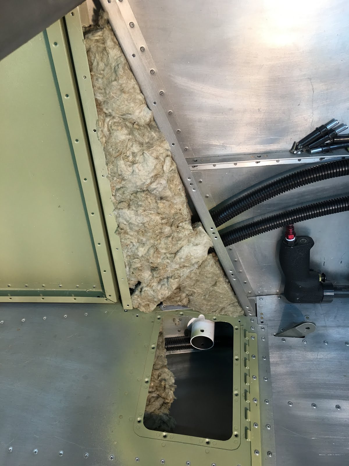
About 2 months have passed, and I have finally made some progress. I placed some insualtion behind the vertical panels, and the conduit. Decided not to do much more, because I will be bolting down the canopy and will need access.

Below shows the side panels in place, and I completed the baggage wall. It was not terribly difficult, a lot of nutplates, primer and screws. It was a fairly precise fit and I needed to trim it slightly for a good fit.

And here is a picture with one of the side panels off. The conduit is accessible here, although I am confident that with the support clamps it should remain in good shape for a long time. Insulation will also be eventually placed.


Another view of the back of the baggage wall and the front. You can see the untrimmed conduits at the bottom.

Now that most of the interior panels are in, I decided to tackle the fuel system in the tunnel. I had previously made a new mounting bracket for the fuel selector. I liked it, but decided I needed more room for the flare nuts. So I made another copy, and rotated the fuel selector 45*, which gave me much better access for tightening the flare nuts.

Another view of the fuel selector upside down. It is a dual selector, top for incoming fuel, and bottom for return. (Could be reverse, any way you would like to plumb it).

This is where I got out the flaring tool and began practicing flares.

This shows the selector installed, and I have the top right/left lines plumbed to the sides of the tunnel. This shows the much better access for tightening the nuts and fittings. The only trick now is that the shaft coming out of the selector is indexed. So the positions for right/left/off will be rotated 45*, kind of weird. So all I have to do is cut, and then TIG weld it back together with the 45* rotation. It seemed like a decent way to do it to me.

And finally after all the lines were finished I pressure tested all of the fuel lines to 75 PSI. I think the highest they will see is 50 PSI, so I am comfortable with that. I also did the brake lines at the same time, running them to 100 PSI.

The first week in January my grandson was in town for a couple of days. After the obligatory trip to Camp Snoopy, he asked if he could sit in my plane. Here is a picture of a very happy young man. I think the grin stayed for a while.

Decided it was time to get the rear seat frames done. For some reason Vans does not do any precision punching on these, no idea why. So I set up a temporary fence on my drill press so that I could get a consistent edge distance as I drilled the backs for the supporting angle stock.

The rear seats were fairly simple and straight-forward. I finished them in a weekend, and forgot to take any mid-stream pictures. I think they are self-explanatory.

I had been delaying buttoning up the front seat floors. I was undecided about running conduit, there was just no good place to exit up front without cutting critical longerons. So I ended up with a short run of conduit at the rear outside. You might be able to see it at the lower right corner of this picture. No big deal, but gives me somewhere to conveniently run wiring to the control stick.

Received some parts from SteinAir, great people in Minnesota. I was very amused at their slogan on my shipping label at left......
And I finally got a chance to start fitting the infamous pink canopy to the fuselage. What a messy, pain in the butt. Unlike Vans precise aluminum parts, this thing was all over the place. Way over sized, needed to be trimmed a lot and was really a challenge. Pictures to come....
November 28, 2016
Interior panels, NACA vents, Click-Bond studs
Trying to keep up momentum, I attempted to finish up the interior panels and some other interior work. Here I am using my right angle drill to attach the right baggage panel to the mid-fuselage longeron. Love that tool....


The two clecos that you see above are attached to these two "L" brackets I made. These keep the side panel from squishing the conduit I placed here. I could have placed them closer to the outer skin, but would have had to really chop up the longeron there. So I went for a very slight bulge in the baggage wall.

Then I fit the baggage wall and match drilled the bulkhead. Removed the baggage wall and here am riveting nutplates so the baggage wall can be screwed on and removed as needed in the future. There will be batteries and equipment back there which will need to be checked often.

This was about the time I got tired of researching the different #'s for the nutplates, both sizes and configurations. So I made up a small board and made a guide. I am much relieved and now don't have to go figure it out every time I need a new one.

This is the panel space ahead of the baggage door, left side of plane. It was time to close this up, so I test fit the panel, and all holes miraculously lined up.
And after confirming fit, I placed some of the Roxul insulation material in the space prior to riveting the panel to the supports.

And now the panel is riveted into place. Mostly pull rivets with a few nutplates on one side.

And finally the access panel in place. I had to make a second smaller access plate in order to get the step bolt in or out. It was a little bit of a head scratcher, but it worked out well. I want to leave the steps out for now, and be able to check and/or replace any nut or bolt in the future. This makes it very accessible, which makes me happy.
 NACA vents.....many builders place two additional vents for the rear seats. I also feel this appropriate, and although relatively simple is scary. In my nice finished fuselage skin I had to cut two big holes for the vents. Measuring twice was mandatory.
 Here is my hole cut, I just made a template from the front factory holes and traced it to the rear fuselage area. After smoothing and deburring the cut, I rough sanded away the primer for a good bond.

Mixed up some ProSeal, a 1 oz. jar from Van's. It is a ProSeal copy from 3M, I don't think it is original ProSeal. Looks and works exactly the same. It is smelly, stinky, gooey and very messy to work with. It pays to take your time, wear gloves and minimize any mess.
 The vents were then buttered up on the inside flange.
Then the vent placed into position. After firm pressure to get a little bit of squeeze out, I added some neodymium magnets to hold them in place. These are the super strong magnets, and they work great to hold things temporarily. I don't think the vents would have moved due to the high viscosity of the ProSeal, but wanted to make sure.

I made a quick detour to fabricate supports for an overhead track of Unistrut. This will carry a trolley and winch (if it all works) to allow me to remove and replace my canopy by myself. It is fairly heavy and awkward, and I don't want to even try by myself to lift it into place. All builders have told me it takes many (30-40) fittings before it is riveted and screwed into place. I used some scrap 2" steel, with nuts welded to end inserts. I am not the prettiest welder but I do fine.

Here is one end bolted to the rafters, unistrut clamped into place. I also made a bracket for the winch, which bolted to the trolley. In the end, the hardest part was getting everything plumb and level.

The other end of the unistrut channel. This is 10' long, plenty of travel to move my canopy on and off.
Click-Bond studs....I needed a way to strap down my conduit so it wouldn't flop around willy nilly. I made a random decision that it needed to be supported every 12", which required it to be somehow strapped down to the skin in a number of places. Some have used self-adhesive zip-tie bases and zip ties, but that doesn't seem to secure or reliable to me. So I purchased some Click-Bond studs, they can be purchased in a variety of base diameters, materials, and applications.

So I had some extra ProSeal left over from the NACA vents, and glued down a few of the studs. The aluminum was scuffed with 60 grit. The plastic carrier has adhesive tape on the feet, and once positioned is attached quite strongly. Then the middle of the plastic carrier is pushed down and it "clicks" into place, holding the stud snugly to the skin while the adhesive sets. ProSeal sets slowly, and stays flexible. I gave this a few days.

After the cure time, the plastic positioner is just ripped off. It is a little scary, because the adhesive on the plastic holds very tighly. But the large surface area on the stud holds very secure.

Some of the adhesive tape stayed behind on this one. It is tenacious, and that is what helps it keep pressure on the stud as the adhesive sets.

And the result is an extremely secure fastener bonded to a flat surface.

A few extra straps were fabricated and primed. These are easily bent around a dowel and I can make 'em up fairly fast.

And the final straps in place on the bonded studs. Extremely secure, lightweight and a good solution.
Going to get busy now finishing all the conduit strapping, installing interior panels and such so I can get on to the canopy.
November 7, 2016
Conduit, Floors, Flaps and Baggage Doors
It has been about six weeks, time to get the blog caught up. I worked on getting the conduit run from the front of the plane to aft, as once the floors are riveted down it is difficult to remove them.
First up was the flap mechanism. It is an electric operated flap setup, and I wanted to get it installed to make sure my conduit runs would not interfere with it. It was not terribly difficult, and basically had it done in a couple of days. I took a small video to demonstrate, although it is not very exciting.
Then I tackled the baggage door, which was slightly out of sequence. Again, wanted to make sure the conduit placement did not impinge on anything.

Here is a picture of the completed (mostly) baggage door. Overall pretty decent fit, although there is a slight bulge vertically from top to bottom. It just doesn't lie perfectly to the fuselage skin. My OCD tendencies are on overdrive, and I think I have figured out how to fix it. But am going to let it sit for a while before I jump in.

Here is a view of the door open, and the lock mechanism in place. I think the lock is a decent fit, but still want to play with it a bit.

And from the inside. It was a tight fit routing the conduit, but it came out nice with no tight bends.

Then I finished routing the conduit through the fuselage and under the back seat floors and baggage areas. Tried to keep away from any sharp bends, and to a minimum number of bends.

This shows the tightest area, which was in front of the baggage door. Also I ran the coax for the comm antennas, which is the small copper coax visible in the lower left.

I mostly used existing holes, placing rubber grommets where needed to reduce the hole size and/or prevent chaffing of the conduit.
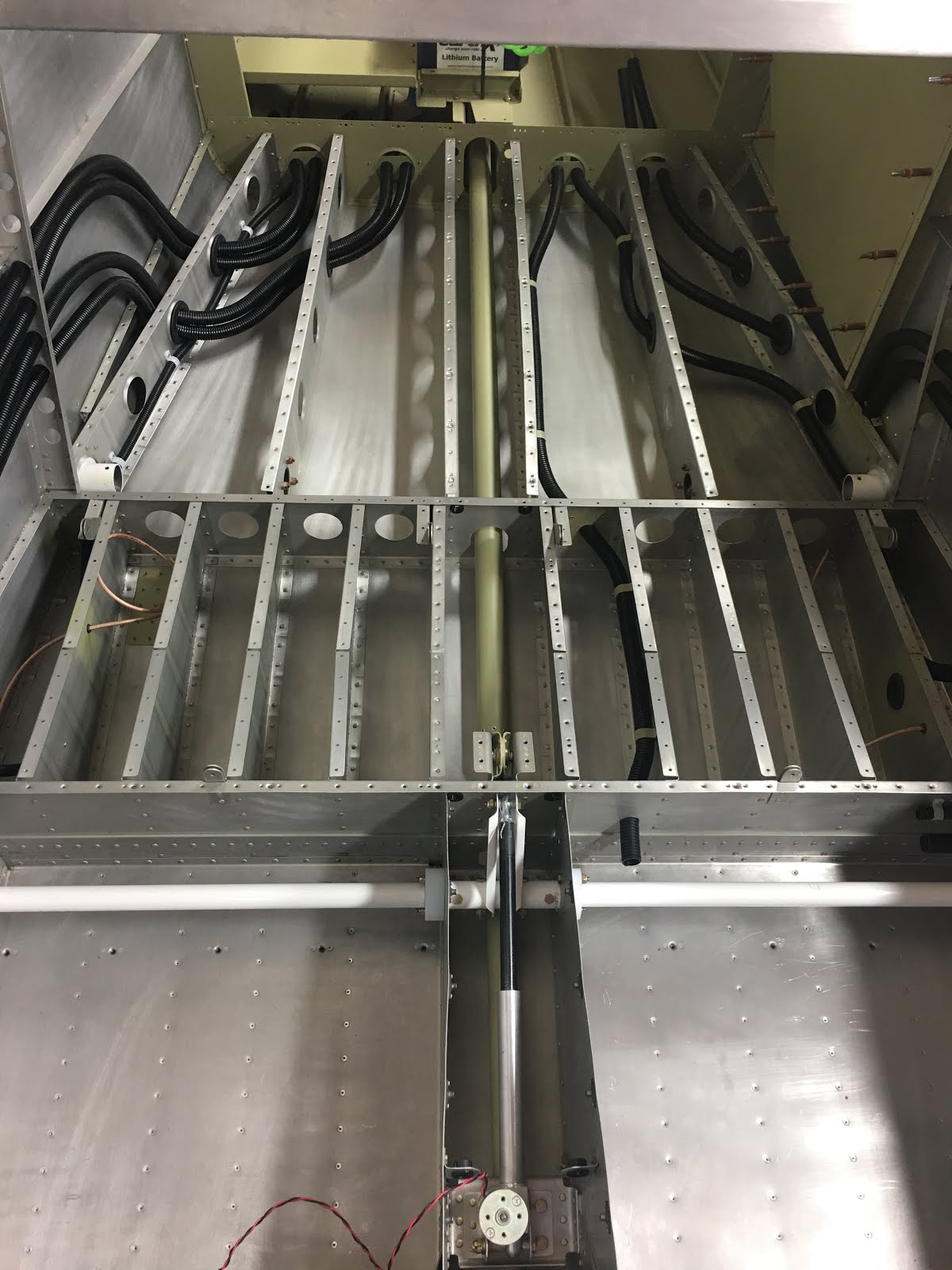
All eight conduits in place and ready to insulate and rivet down the flooring.
Then the conduit was strapped down wherever it ran unsupported more than 12". I could not find a suitable "off the shelf" strap/bracket, so I made my own. Very simple, just aluminum strips cut and bent for the 3/4' OD of the conduit. Worked great.
And finally I placed some insulation/sound barrier material in the cavities before riveting the floors down. After a lot of research, I came up with a product called Roxul Safe'n'Sound. It is made for exactly what I need, both insulation and sound barrier. It is non-combustible, with a melting point of 2150*. Just to make sure, I put a MAPP torch to it, and it would not ignite, I could only make it melt. Kind of cool stuff. For fun I put a torch to fiberglass insulation, it burned just fine.....not a good choice there. Roxul is a mineral wool, it just doesn't burn.
 Another big plus is that this stuff is at the Home Depot and priced reasonably. So I bought a bundle of it, and will probably only use half. Will use any leftover on the shop! Even though it is lightweight, I only used it to a maximum of 3 1/2". It will add a few pounds to the plane, and would like to keep it to a minimum.

 I then had to finish the bulkhead doublers for the passenger side. This went a LOT quicker, as I had the design already established from the previous side.

A "selfie" of yours truly riveting the bulkhead doublers. It is a tight space, and required a lot of gymnastics to get it all done. A close examination of the above rivets show a few smiley rivets, but not many. I elected to leave a few as drilling out was even a worse bet. I think this is way over engineered, and am quite confident it will hold up just fine. I have seen builders without any doublers.

And finally before putting down the floors I had to cut out access holes for the conduit. These areas will be covered by interior panels, so not to worry about exposed conduit. The holes were measured, drilled, and cut out to the edge. Then polished and primed.

This shows the pilot side seat floor and baggage area riveted down, starting to insulate the other side.

And finally, everything in and riveted down. The small green primed plates are inspection/access panels. The back ones are for the step attachments, and the more anterior ones are where the comm antenna access is needed.
A number of small items to finish up, then it is time to start fitting the large pink fiberglass canopy top. It is about to start looking like an aircraft!
September 22, 2016
Slow progress on the plane since about June. I have not been able to devote the time I would like to the project due to health issues. Hopefully I will be able to increase time in the near future.
For a brief explanation, I had a nasty respiratory infection in June. After three rounds of antibiotics it finally went away, but I was left feeling pretty uncomfortable. Body aches, joint aches and the such. Finally at the end of September I could not even walk at times due to the right foot. Worse, I could not rivet because my shoulders ached!
After multiple docs and blood tests, I have received the exciting diagnosis of rheumatoid arthritis. Lots of medications and I still am not prime time. But the doc assures me that given a few more months they will zero in on the right cocktail of meds to make me feel somewhat normal again. It could be worse, and am doing my best to continue on despite. Enough of that crap.
Conduit Holes
Many months ago I saw a few different posts from builders who had run additional conduit down the side of the plane besides the two holes Van's provides. I am a big fan of extra conduit and laid out where I would like to place them. I walked away from it for a time, thinking I should probably check with Van's first before I start drilling holes in the bulkheads.
 So on one stoopid day I was drilling holes and I drilled away on those laid out holes, and did a beautiful job. Then I remembered I was going to check with Van's. Oops. So I sent a picture into Van's support and asked them for direction.
The response I received was that since Vans has not tested this modification, and would not be doing it for me, they could not approve or disapprove. I am on my own. I was advised..... "to consult AC 43.13-1B - Acceptable Methods, Techniques, and Practices - Aircraft Inspection and Repair and you can determine for yourself what doubler arrangement would be necessary.

I actually think that is a pretty fair response, and have no argument with it. So I dove into the FAA advisory, which includes repair and doublers. I broadened my education, and after a number of possible iterations came up with the following to strengthen the bulkhead I drilled out. I started with by bending a bunch of doubler plates to see what worked. You can see I made a lot of trial and error. I then marked out a bunch to bend, and even then changed my mind.
I eventually decided to place two doublers, one on each side. I wanted to err on the side of overkill, and this should do it. I also ended up extending one all the way down the bulkhead, and adding one small hole for my comm coax cable. What the heck. The two bulkheads I drilled out are different widths so I had to use different width doublers. That also resulted in different hole patterns.


The above shows doublers I made for the right (pilot) side of the plane. Two for each bulkhead, different widths and hole patterns. Some of the criteria I used from the FAA advisory:
-similar type and thickness aluminum
-bends at right angles to the grain
-edge holes at least 2d from center of hole to edge (twice the width of rivet hole, 1/8")
-field holes either 3d or 4d
-all corners and edges rounded
-all deburred and polished

Here are the bulkheads now match drilled for the doublers. It is a bit disorienting here, the skin is the side of the plane, and the gold anodized parts are the wing spars towards the bottom.
Here are my parts ready for primer, all scuffed with Scotchbrite pads and Prekote conditioner. And after a coat of Azko primer. I also touched up the control tube pivot which is in the picture. It was rubbing on it's hinge mount, and I had to tweak it.


Here are views of the doublers riveted in place to the bulkheads. I flexed them by hand before and after. They are way stiffer now, I have no longer have worries about bulkhead strength. But it was a buttload of work and probably not worth all the hassle and stress. Live and learn.


August 15, 2016
Battery Box Modification
Last entry is about a month old. I have wrestled with a nasty virus and progress has been slow, but finally got the battery box done. I will start where I left off. After a while I will put this on it's own page in chronological order.

Here are the mounting rails for the battery box and accessory tray. All of the unpainted parts are my own design and fabrication. It is not rocket science, but it is dang difficult to match stuff up exactly to existing framework, and tie it all in structurally.

And here is the accessor tray in place on top of the mounting rails. It is a lot of real estate, but I have a feeling that I might be using most of it for ELT and various electronics. The RV-10 is notorious for being a bit nose heavy if anything, so any remote electronic boxes would do well here.

The final structural part of the battery box are the front and back sides to hold the battery in place. I drew out on aluminum the part as best I could visualize, and began cutting it out......

Sectioning the "ears" off of the sheet so that I can make a box on the pan brake.

All internal and external corners radiused and polished up. I also tried to make sure the grain of the aluminum was perpendicular to the long axis, which will have less chance of cracking. (Ask me how I learned about that).

I removed one of the beaks on the brake, so that my box would wrap around when I made the second set of bends. Here I line up for the first bend on the end.

First I bent the two smaller ends on each end of the tray....

Easy to see here the two end bends in place so that they will clear the beaks on the bending brake......

And starting to bend one of the long sides, while making sure the end bends slip past the ends of the beaks.....

And now both long sides bent so somewhat of a box is created. This stiffens the part significantly, and is probably overkill for the battery box sides. But better stout than not.

Here are both front and back of the box in place after bending on the brake. They fit well, although the front one is slightly "open" as it is a bit short. I made another and it was too long, so I decided in the end to just place a small shim there. My time and patience have a limit.

And finally the final test fit with my "dummy" batteries. These are just hollow cases, but great for fabrication purposes. Everything fits, and all attached with screws, bolts and clecoes at this stage. So time to dismantle for deburring, polishing, scuffing and primer. (I think I have taken this in and out about a dozen times during the process).

After prep, all parts got primed with the Azko primer. I also touched up the bellcrank mount which had to be cut and got scuffed up a bit.

All parts cured and ready to assemble. I used a lot of different combinations of rivets and nutplates in the construction. Rivet everywhere possible for strength, but some bolts and screws so that the bellcrank mount and accessory tray could be removed if needed. I will probably cut some larger lightening holes in the tray after my components are arranged.

I riveted everything on the bench, leaving the last pulled rivets and bolts/screws for inside the plane.

And at last everything back in place, and by luck it all fit again.

\
And with the dummy batteries in place and the hold down snugged up. After everything was riveted, bolted and screwed down, it is tight and solid. Very happy with this, although it took a lot of time.
And I have to sing the praises for my "Tight Fit" drill kit. I received this tool with my initial tool kit and thought it might be a fluff item. Far from it, this allows me to get to areas I could not otherwise access. Just chuck it up into a drill and it is easy to hold onto and drill right up next to things. Great tool!


July 11, 2016
I have decided to "double down" and increase my battery potential. Vans plans call for one battery, and most people go for two especially in an all electric aircraft like I am planning. One theory is primary battery and backup. At this point I think I am going with two complete and separate isolated busses. If I can configure things correctly, I could lose one buss entirely and still fly safely (to the next airport). It would be unusual to lose everything, maybe just an alternator or battery. But I am hoping this is belt and suspenders.
A typical battery for this plane is an Odyssey 925, which gives 24 Amp hours for 26 lbs. of lead. Newer LiFePO4 batteries are available with a much better life span, hold charges longer, are lighter and hold a bigger charge.
 I intend to place two batteries for redundant battery power. Here are a couple of EarthX's Lithium batteries. These are actually just empty shells provided by EarthX so that I can accurately build my battery containment box.
These are their ETX1200 models, and each are designed with a redundant battery management chip that protects against overcharging, over discharging, short circuit protection and helps balance the cells.
Both of these combined weigh only 15 lbs. and combined provide 50 Amp hours of current! If the loss of 11lbs. screws up my weight and balance I will gladly throw in a set of tools to the baggage compartment.
Losing 11 lbs. and gaining 26 amp hours sounds like a deal I can't pass up.

So here is a view of where the battery(s) will sit. This is the stock battery tray, I went ahead and built it per the plans knowing I would probably change things. It is a stiff piece that is also support for the elevator bellcrank mechanism you can see behind it. The control tube runs underneath it.

Step 1: Remove battery and bellcrank mount, place on workbench and scratch head.
I decided to cut off the right/starboard/passenger (never know which term to use)side of the box and extend out to the right. I will also at the same time construct an auxillary equipment tray for electronic devices hidden in the tail section along with these batteries.
 So I used a small graphics program on my iPad to draw out the supports (2) I would need. It was a big help to do this digitally. I made a lot of changes as I measured and snuck up on a final design concept. Probably simple, but I get tired of burning through aluminum.
The far lip of the support will support the edge of the auxillary tray. I needed to raise the tray up about 3/4" in order to use the stiffener on the fuselage wall to support the far outboard end.

 So the piece above was cut out and marked prior to bending. To the right is after a trip to the pan brake bender I have. I never used it too often before the plane. Now you could not take it from me. Nice, even square bends.
Drilled some attach holes for rivets, and clecoed these to the bellcrank ribs with the tops flush with the bellcrank rails. When all is tied together it should be plenty sturdy to support another 2 1/2 inches of battery width.

Battery tray/bellcrank mount placed back in position. The right side of the battery tray (top side in picture) has been removed so that I can now extend the tray out to the limits of the supports. Front and back rails also to be fabricated to the new width.

This is somewhat of a preview of how the new batteries will sit. I do have a much better plan for the battery hold-down than the large rubber band.
Flooring and Inspection Panels
Have received a lot of advice on insulation/sound reduction materials. A great idea, as rapping on the aluminum skin can make the aircraft sound like a giant drum. And insulation should help both with the hot and cold. I did a LOT of research trying to find a fireproof/safe material to use. The bar was somewhat 2000* before ignition. I figured that was safe. So I settled on a product called Roxul, which ignites at 2150*, and is available at the Home Depot (aka Aircraft Depot). It is a rock wool product, a little more awkward to work with than fiberglass, but similar.

Here is the passenger side back floor with one strip of the Roxul laid in. It can be gently pulled apart and cut/massaged into place. Then the floor pieces located back down, clecoed and riveted into place. I am leaving some open right now to facilitate wiring/conduit placement.


And I finished the installation of the tunnel inspection plates. They will allow access to the tunnel from the sides without removing the middle console. The fuel boost pump(s) and filters will be located there and need annual condition inspection.


I also spent almost two full days organizing, screws, nuts, bolts, stainless steel hardware, cotter pins and such. It was a huge amount of time, but will hopefully end the two hours of searching everytime I need a specific bolt, locknut and washer.
 As a questionable bonus, I actually had to learn the meaning of the different specifications. The AN (Army/Navy) nomenclature seems to make more sense to me. The MS (Military Spec) is a lot of numbers and is a bit boggling. When possible I put both specs on the label for the same item.
Fuel Selector
Vans fuel selector is very stock, and pretty unappealing. It also does not allow for fuel return (duplex) which I want to install. A duplex selector might be used for EFI (electronic fuel injection), for a purge line to avoid hot starts, or could just cap it off if I decide not to use it. At any rate it is a lot easier to install now rather than later.

Here is a picture of Vans stock fuel selector valve. My thoughts were that it looks like it belongs on my water heater.

And here is my new duplex valve. I will use the upper half for fuel return and the lower half for supply, although it really is arbitrary. Made in the UK by Andair, they did a great job. I specified exactly what I wanted, which was nice. The only painful part was the 3 month wait, but I'm in no hurry. Now for fitting it to the plane.....

This is the mounting plate for the stock fuel selector. None of the holes line up for the Andair valve, so I started removing it here.

So this shows how poorly this mounting plate fits the new valve. No biggee, time to make up a new one. Grabbed some .063 aluminum and fabbed up a new one pretty quickly.

So new plate installed, and the valve mount to it. Everything looks good to me. I talked to a few fellow builders, and the consensus is to run flexible lines from the side ports to the blue AN fittings in the tunnel. So I started a conversation with a great guy who makes these, Tom. Tom tells me we have clearance issues to place elbow fittings on the valve. Crap! So after days of head-scratching, I come up with the following.....
I rotated the valve 45*, giving the elbow fittings room both from and back. Tom sent me these elbow fittings to try, they will have flexible hose attached at the end, which will have plenty of room. The only rub is that the indicator knob will now be oriented 45* off center. I think that if I cut the extension shaft (long purple shaft 4 pics above), rotate 45* back to center and TIG weld it together again, problem solved. A bit of a dance, but it should work well.


So this shows the valve rotated from above, and the fuel filter/boost pump zip tied in place to get an idea on spacing. This solution (rotated) will work, now I get to make another mounting plate since this one doesn't fit. Sheesh.
Will try and keep this updated when I get the new mount in place and everything working again...
Parking Brake
There is no provision in the "stock" build for a parking brake. Having flown planes with and without, I can definitely say I want a parking brake. For runups, extended holds due to tower/ground requests, or simply parking on an incline.........a parking brake is a very welcome item.


The standard brake bracket is on the left. This is just an L bracket to which one can attach the brake lines/AN fittings.
On the right I have started to drill out the rivets from the opposite side of the firewall for installation of the new bracket.

Here is a view of the parking brake mechanism. Very simple, after pressure is applied to the brake lines from either pilot or passenger, the brake is actuated via a simple arm. This then holds the pressure static to keep the brakes engaged. Upon release of the actuator arm, pressure falls off.

And now the parking brake is riveted on the inside of the firewall. I have protective caps in place, notice all of the aluminum powder on everything. A dirty environment right now.
The push/pull cable sheath will be clamped in the rubber clamp, and the wire cable is secured by the gold cylinder via the screw The gold colored arm actuates the brake by moving right/left. Simple and reliable. (These are actually all cadmium plated).
I am going to start running the brake lines soon.

A few days later, Dean Carver came by to help me figure out running brake lines and how to flare fittings properly. Dean is welder extraordinaire, car builder and a great guy. Here Dean is beginning to lay out the aluminum brake lines prior to cutting to length and flaring for the AN fittings.
I had never really flared anything, so it was great to get a good tutorial from Dean on the fine points. It took us about 3 hours to lay them out and flare. I now feel I could tackle the job on my own. Thanks, Dean!

Here is a view of the brake lines running along the back of the firewall, down into the tunnel. The "T" duct is a heater duct that they pass underneath.

And this is a more comprenesive view of the brake lines. They run from the parking brake, through the tunnel, and then after a 90 degree fitting out to the landing gear exit.
Rotisserie??
I know, it sounds like I am talking BBQ. But many aircraft builders have adopted what custom car builders have. A rotisserie is fabricated to suspend front and aft. Then the entire fuselage can be rotated to facilitate fabrication and access.

This is the front end view with the fuselage mount in place. I welded up the yellow bracket that is bolted to the firewall. The yellow gizmo circled in red is a part I purchased from a builder/manufacturer. His setup was cheaper to buy pre-made, and saved me a weekend.

This is the plane suspended on the rotisserie, with my trusted companion serving as quality assurance. The back mount is just a pipe bolted onto some plywood to the aft deck. It is not perfectly symmetrical, so it doesn't rotate with a flick of the wrist. But with just a little muscle, I can turn it anywhere I want, and then lock it in place.

This shows how much easier it is to do riveting when the fuselage is tilted on it's side. With the ability to turn it around, it was much easier to rivet. Dr. Marc Haney came by and helped me rivet away and join the tailcone to the fuselage. Now I have a big canoe.

Here I am riveting the baggage floor supports to the front tailcone bulkhead. Way easier with this dude tilted to one side. I had to reach over and in a bit, but way better than upside down.
It still amazes me how precisely things come together. I had expected a lot of fudge factor and making things work that were less than ideal. To date everything is extremely accurate and precise.
Step Bushings
The steps for the RV-10 are located near the trailing edge of the wing, making it much easier to step up onto the wing to enter the plane. They are a one-piece welded aluminum assembly, that slides into a steel tube. The step is retained by a single bolt passed through both pieces and secured with a locknut.
Some RV-10's have had a problem with the locknut coming loose. The general consensus is that it is difficult to torque down tightly because the tube/step combination flexes and collapses with any significant torque. Many builders as a result have placed a bushing in the step so that the bolt can be torqued down tightly. I figured now is the time, and I made my own bushings rather than buy some aftermarket version. (what fun is buying them pre-made?)

So I chucked up a piece of 6061-T6 aluminum, and turned it to the inside dimension of the step. I have a couple of huge cylinders of this stuff given to me by a patient, Randy Felten. Thanks Randy!

And here I am drilling the bolt hole through the material, doing this twice.

And afterwards I parted off the two bushings I would need. The holes were a tad undersized so I could final drill them in place.

And then I used the mill to shave down the size, as they didn't need to be so dang big. Should cut down the weight a little bit. Used the bolt hole for alignment, although it really didn't matter.

Now almost completed. The right dimension to slide down in the step tube, Cut down to reduce the bulk a bit, and drilled for the bolt hole.
On trying one in, it was a pretty tight fit, which is what I want. The challenge is that proper placement is down the tube about 10".

So I tapped the side for a 1/4" thread, and did the same on a long piece of drill rod. As a result, I can carry it down the tube, and even rotate it around to the right orientation. Once in place, I can secure it with a temporary bolt and back out the drill rod. It worked fine.

Here is a picture of the access panel I fabricated in order to access the step bolt in the future. This is in the front of the baggage area. I had to notch the access plate so that the bolt could be removed if needed. It comes straight up and there was no other way to do it that I could see. But it worked fine.

This is the bushing, screwed onto the "insertion tool", and the step tube that it will go into. It is a snug fit, but can be wrangled around enough to get into place.

Step bushing inserted, before the tool has been unscrewed.

Now the step has been inserted from the outside of the fuselage. There is an inner brace that holds the inside end of the step. The steel fitting on the fuselage (powder coated white) was final drilled with the bushing/step lined up. Finally the bolt is dropped in, everything fits great and can be torqued tightly.
BTW, that is the comm antenna doubler just to the left. Ready to rivet that in place soon.

Not sure if one more view is necessary, but.....

And here is how the outside of the step looks, with the plane tilted over to work on. The step is a great feature, wish one was on the RV-6A of John's that I fly. However, during construction it is a shin-buster. Since I have access via the inspection plate, I will remove until final assembly.
Tuesday, April 19th
Fuselage and Wings have arrived!
My Quick-build wings and fuselage arrived a few weeks ago. They had a long journey from Oregon to the Phillipines, where they were assembled at an aircraft manufacturing plant. Then they were put on a boat back to Oregon again, where Vans Aircraft inspected them. Once they were "blessed" by Vans, they were put on a truck and shipped down to me.
I had a rolling cart made for each of them, and unloading and storage was fairly easy. The hard part was talking Julie out of some garage space for my wings for the time being.
Both assemblies are about 90% completed. They allow for me to do a lot of plumbing/wiring before I finally close them up. This is a big boost in my time-line and helps a bunch.
And I also just received from the FAA notice that I have successfully reserved......
N12CL!
Although reserved but not yet committed, I think it is an excellent N# for my aircraft. It rolls off the tongue pretty easy....November one, two, charlie, lima. I just need to keep it reserved until it would be time to register at the end of the build. Hmmmm.

Here is the fuselage, sitting in my shop. I began by removing the floorboards (where my drill is sitting in the photo). There were only temporary rivets placed, as I am required to remove them to rivet both halves of the fuselage together properly. (Please note FOX News on the TV, with nauseating political news).
Here are pics of the two halves clecoed together, ready for final drilling and assembly.....


Slow progress on the plane since about June. I have not been able to devote the time I would like to the project due to health issues. Hopefully I will be able to increase time in the near future.
For a brief explanation, I had a nasty respiratory infection in June. After three rounds of antibiotics it finally went away, but I was left feeling pretty uncomfortable. Body aches, joint aches and the such. Finally at the end of September I could not even walk at times due to the right foot. Worse, I could not rivet because my shoulders ached!
After multiple docs and blood tests, I have received the exciting diagnosis of rheumatoid arthritis. Lots of medications and I still am not prime time. But the doc assures me that given a few more months they will zero in on the right cocktail of meds to make me feel somewhat normal again. It could be worse, and am doing my best to continue on despite. Enough of that crap.
Conduit Holes
Many months ago I saw a few different posts from builders who had run additional conduit down the side of the plane besides the two holes Van's provides. I am a big fan of extra conduit and laid out where I would like to place them. I walked away from it for a time, thinking I should probably check with Van's first before I start drilling holes in the bulkheads.
 So on one stoopid day I was drilling holes and I drilled away on those laid out holes, and did a beautiful job. Then I remembered I was going to check with Van's. Oops. So I sent a picture into Van's support and asked them for direction.
The response I received was that since Vans has not tested this modification, and would not be doing it for me, they could not approve or disapprove. I am on my own. I was advised..... "to consult AC 43.13-1B - Acceptable Methods, Techniques, and Practices - Aircraft Inspection and Repair and you can determine for yourself what doubler arrangement would be necessary.

I actually think that is a pretty fair response, and have no argument with it. So I dove into the FAA advisory, which includes repair and doublers. I broadened my education, and after a number of possible iterations came up with the following to strengthen the bulkhead I drilled out. I started with by bending a bunch of doubler plates to see what worked. You can see I made a lot of trial and error. I then marked out a bunch to bend, and even then changed my mind.
I eventually decided to place two doublers, one on each side. I wanted to err on the side of overkill, and this should do it. I also ended up extending one all the way down the bulkhead, and adding one small hole for my comm coax cable. What the heck. The two bulkheads I drilled out are different widths so I had to use different width doublers. That also resulted in different hole patterns.


The above shows doublers I made for the right (pilot) side of the plane. Two for each bulkhead, different widths and hole patterns. Some of the criteria I used from the FAA advisory:
-similar type and thickness aluminum
-bends at right angles to the grain
-edge holes at least 2d from center of hole to edge (twice the width of rivet hole, 1/8")
-field holes either 3d or 4d
-all corners and edges rounded
-all deburred and polished

Here are the bulkheads now match drilled for the doublers. It is a bit disorienting here, the skin is the side of the plane, and the gold anodized parts are the wing spars towards the bottom.
Here are my parts ready for primer, all scuffed with Scotchbrite pads and Prekote conditioner. And after a coat of Azko primer. I also touched up the control tube pivot which is in the picture. It was rubbing on it's hinge mount, and I had to tweak it.


Here are views of the doublers riveted in place to the bulkheads. I flexed them by hand before and after. They are way stiffer now, I have no longer have worries about bulkhead strength. But it was a buttload of work and probably not worth all the hassle and stress. Live and learn.


August 15, 2016
Battery Box Modification
Last entry is about a month old. I have wrestled with a nasty virus and progress has been slow, but finally got the battery box done. I will start where I left off. After a while I will put this on it's own page in chronological order.

Here are the mounting rails for the battery box and accessory tray. All of the unpainted parts are my own design and fabrication. It is not rocket science, but it is dang difficult to match stuff up exactly to existing framework, and tie it all in structurally.

And here is the accessor tray in place on top of the mounting rails. It is a lot of real estate, but I have a feeling that I might be using most of it for ELT and various electronics. The RV-10 is notorious for being a bit nose heavy if anything, so any remote electronic boxes would do well here.

The final structural part of the battery box are the front and back sides to hold the battery in place. I drew out on aluminum the part as best I could visualize, and began cutting it out......

Sectioning the "ears" off of the sheet so that I can make a box on the pan brake.
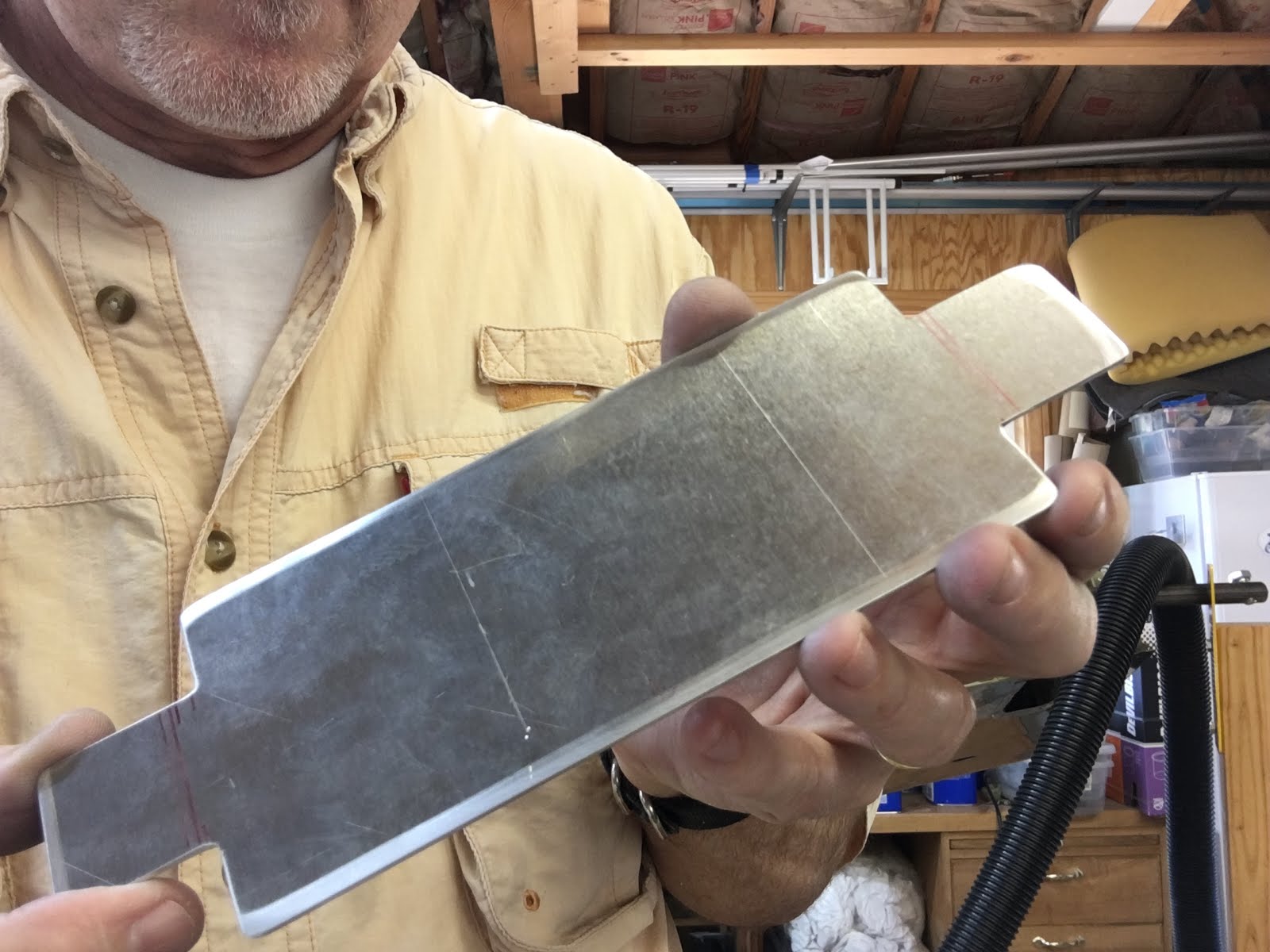
All internal and external corners radiused and polished up. I also tried to make sure the grain of the aluminum was perpendicular to the long axis, which will have less chance of cracking. (Ask me how I learned about that).

I removed one of the beaks on the brake, so that my box would wrap around when I made the second set of bends. Here I line up for the first bend on the end.

First I bent the two smaller ends on each end of the tray....

Easy to see here the two end bends in place so that they will clear the beaks on the bending brake......

And starting to bend one of the long sides, while making sure the end bends slip past the ends of the beaks.....

And now both long sides bent so somewhat of a box is created. This stiffens the part significantly, and is probably overkill for the battery box sides. But better stout than not.

Here are both front and back of the box in place after bending on the brake. They fit well, although the front one is slightly "open" as it is a bit short. I made another and it was too long, so I decided in the end to just place a small shim there. My time and patience have a limit.

And finally the final test fit with my "dummy" batteries. These are just hollow cases, but great for fabrication purposes. Everything fits, and all attached with screws, bolts and clecoes at this stage. So time to dismantle for deburring, polishing, scuffing and primer. (I think I have taken this in and out about a dozen times during the process).

After prep, all parts got primed with the Azko primer. I also touched up the bellcrank mount which had to be cut and got scuffed up a bit.

All parts cured and ready to assemble. I used a lot of different combinations of rivets and nutplates in the construction. Rivet everywhere possible for strength, but some bolts and screws so that the bellcrank mount and accessory tray could be removed if needed. I will probably cut some larger lightening holes in the tray after my components are arranged.

I riveted everything on the bench, leaving the last pulled rivets and bolts/screws for inside the plane.

And at last everything back in place, and by luck it all fit again.

\
And with the dummy batteries in place and the hold down snugged up. After everything was riveted, bolted and screwed down, it is tight and solid. Very happy with this, although it took a lot of time.
And I have to sing the praises for my "Tight Fit" drill kit. I received this tool with my initial tool kit and thought it might be a fluff item. Far from it, this allows me to get to areas I could not otherwise access. Just chuck it up into a drill and it is easy to hold onto and drill right up next to things. Great tool!


July 11, 2016
I have decided to "double down" and increase my battery potential. Vans plans call for one battery, and most people go for two especially in an all electric aircraft like I am planning. One theory is primary battery and backup. At this point I think I am going with two complete and separate isolated busses. If I can configure things correctly, I could lose one buss entirely and still fly safely (to the next airport). It would be unusual to lose everything, maybe just an alternator or battery. But I am hoping this is belt and suspenders.
A typical battery for this plane is an Odyssey 925, which gives 24 Amp hours for 26 lbs. of lead. Newer LiFePO4 batteries are available with a much better life span, hold charges longer, are lighter and hold a bigger charge.

These are their ETX1200 models, and each are designed with a redundant battery management chip that protects against overcharging, over discharging, short circuit protection and helps balance the cells.
Both of these combined weigh only 15 lbs. and combined provide 50 Amp hours of current! If the loss of 11lbs. screws up my weight and balance I will gladly throw in a set of tools to the baggage compartment.
Losing 11 lbs. and gaining 26 amp hours sounds like a deal I can't pass up.

So here is a view of where the battery(s) will sit. This is the stock battery tray, I went ahead and built it per the plans knowing I would probably change things. It is a stiff piece that is also support for the elevator bellcrank mechanism you can see behind it. The control tube runs underneath it.

Step 1: Remove battery and bellcrank mount, place on workbench and scratch head.
I decided to cut off the right/starboard/passenger (never know which term to use)side of the box and extend out to the right. I will also at the same time construct an auxillary equipment tray for electronic devices hidden in the tail section along with these batteries.
 So I used a small graphics program on my iPad to draw out the supports (2) I would need. It was a big help to do this digitally. I made a lot of changes as I measured and snuck up on a final design concept. Probably simple, but I get tired of burning through aluminum.
The far lip of the support will support the edge of the auxillary tray. I needed to raise the tray up about 3/4" in order to use the stiffener on the fuselage wall to support the far outboard end.

 So the piece above was cut out and marked prior to bending. To the right is after a trip to the pan brake bender I have. I never used it too often before the plane. Now you could not take it from me. Nice, even square bends.
Drilled some attach holes for rivets, and clecoed these to the bellcrank ribs with the tops flush with the bellcrank rails. When all is tied together it should be plenty sturdy to support another 2 1/2 inches of battery width.

Battery tray/bellcrank mount placed back in position. The right side of the battery tray (top side in picture) has been removed so that I can now extend the tray out to the limits of the supports. Front and back rails also to be fabricated to the new width.

This is somewhat of a preview of how the new batteries will sit. I do have a much better plan for the battery hold-down than the large rubber band.
Flooring and Inspection Panels
Have received a lot of advice on insulation/sound reduction materials. A great idea, as rapping on the aluminum skin can make the aircraft sound like a giant drum. And insulation should help both with the hot and cold. I did a LOT of research trying to find a fireproof/safe material to use. The bar was somewhat 2000* before ignition. I figured that was safe. So I settled on a product called Roxul, which ignites at 2150*, and is available at the Home Depot (aka Aircraft Depot). It is a rock wool product, a little more awkward to work with than fiberglass, but similar.
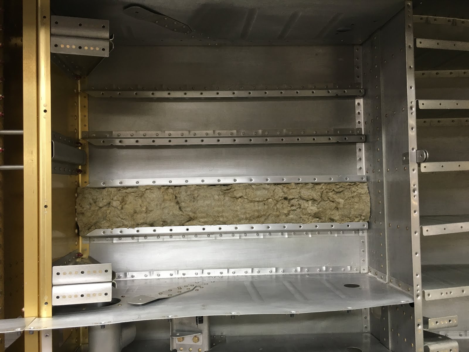
Here is the passenger side back floor with one strip of the Roxul laid in. It can be gently pulled apart and cut/massaged into place. Then the floor pieces located back down, clecoed and riveted into place. I am leaving some open right now to facilitate wiring/conduit placement.


And I finished the installation of the tunnel inspection plates. They will allow access to the tunnel from the sides without removing the middle console. The fuel boost pump(s) and filters will be located there and need annual condition inspection.


I also spent almost two full days organizing, screws, nuts, bolts, stainless steel hardware, cotter pins and such. It was a huge amount of time, but will hopefully end the two hours of searching everytime I need a specific bolt, locknut and washer.
 As a questionable bonus, I actually had to learn the meaning of the different specifications. The AN (Army/Navy) nomenclature seems to make more sense to me. The MS (Military Spec) is a lot of numbers and is a bit boggling. When possible I put both specs on the label for the same item.
Fuel Selector
Vans fuel selector is very stock, and pretty unappealing. It also does not allow for fuel return (duplex) which I want to install. A duplex selector might be used for EFI (electronic fuel injection), for a purge line to avoid hot starts, or could just cap it off if I decide not to use it. At any rate it is a lot easier to install now rather than later.

Here is a picture of Vans stock fuel selector valve. My thoughts were that it looks like it belongs on my water heater.

And here is my new duplex valve. I will use the upper half for fuel return and the lower half for supply, although it really is arbitrary. Made in the UK by Andair, they did a great job. I specified exactly what I wanted, which was nice. The only painful part was the 3 month wait, but I'm in no hurry. Now for fitting it to the plane.....

This is the mounting plate for the stock fuel selector. None of the holes line up for the Andair valve, so I started removing it here.

So this shows how poorly this mounting plate fits the new valve. No biggee, time to make up a new one. Grabbed some .063 aluminum and fabbed up a new one pretty quickly.

So new plate installed, and the valve mount to it. Everything looks good to me. I talked to a few fellow builders, and the consensus is to run flexible lines from the side ports to the blue AN fittings in the tunnel. So I started a conversation with a great guy who makes these, Tom. Tom tells me we have clearance issues to place elbow fittings on the valve. Crap! So after days of head-scratching, I come up with the following.....
I rotated the valve 45*, giving the elbow fittings room both from and back. Tom sent me these elbow fittings to try, they will have flexible hose attached at the end, which will have plenty of room. The only rub is that the indicator knob will now be oriented 45* off center. I think that if I cut the extension shaft (long purple shaft 4 pics above), rotate 45* back to center and TIG weld it together again, problem solved. A bit of a dance, but it should work well.


So this shows the valve rotated from above, and the fuel filter/boost pump zip tied in place to get an idea on spacing. This solution (rotated) will work, now I get to make another mounting plate since this one doesn't fit. Sheesh.
Will try and keep this updated when I get the new mount in place and everything working again...
Parking Brake
There is no provision in the "stock" build for a parking brake. Having flown planes with and without, I can definitely say I want a parking brake. For runups, extended holds due to tower/ground requests, or simply parking on an incline.........a parking brake is a very welcome item.


The standard brake bracket is on the left. This is just an L bracket to which one can attach the brake lines/AN fittings.
On the right I have started to drill out the rivets from the opposite side of the firewall for installation of the new bracket.

Here is a view of the parking brake mechanism. Very simple, after pressure is applied to the brake lines from either pilot or passenger, the brake is actuated via a simple arm. This then holds the pressure static to keep the brakes engaged. Upon release of the actuator arm, pressure falls off.

And now the parking brake is riveted on the inside of the firewall. I have protective caps in place, notice all of the aluminum powder on everything. A dirty environment right now.
The push/pull cable sheath will be clamped in the rubber clamp, and the wire cable is secured by the gold cylinder via the screw The gold colored arm actuates the brake by moving right/left. Simple and reliable. (These are actually all cadmium plated).
I am going to start running the brake lines soon.

A few days later, Dean Carver came by to help me figure out running brake lines and how to flare fittings properly. Dean is welder extraordinaire, car builder and a great guy. Here Dean is beginning to lay out the aluminum brake lines prior to cutting to length and flaring for the AN fittings.
I had never really flared anything, so it was great to get a good tutorial from Dean on the fine points. It took us about 3 hours to lay them out and flare. I now feel I could tackle the job on my own. Thanks, Dean!

Here is a view of the brake lines running along the back of the firewall, down into the tunnel. The "T" duct is a heater duct that they pass underneath.

And this is a more comprenesive view of the brake lines. They run from the parking brake, through the tunnel, and then after a 90 degree fitting out to the landing gear exit.
Rotisserie??
I know, it sounds like I am talking BBQ. But many aircraft builders have adopted what custom car builders have. A rotisserie is fabricated to suspend front and aft. Then the entire fuselage can be rotated to facilitate fabrication and access.

This is the front end view with the fuselage mount in place. I welded up the yellow bracket that is bolted to the firewall. The yellow gizmo circled in red is a part I purchased from a builder/manufacturer. His setup was cheaper to buy pre-made, and saved me a weekend.

This is the plane suspended on the rotisserie, with my trusted companion serving as quality assurance. The back mount is just a pipe bolted onto some plywood to the aft deck. It is not perfectly symmetrical, so it doesn't rotate with a flick of the wrist. But with just a little muscle, I can turn it anywhere I want, and then lock it in place.

This shows how much easier it is to do riveting when the fuselage is tilted on it's side. With the ability to turn it around, it was much easier to rivet. Dr. Marc Haney came by and helped me rivet away and join the tailcone to the fuselage. Now I have a big canoe.

Here I am riveting the baggage floor supports to the front tailcone bulkhead. Way easier with this dude tilted to one side. I had to reach over and in a bit, but way better than upside down.
It still amazes me how precisely things come together. I had expected a lot of fudge factor and making things work that were less than ideal. To date everything is extremely accurate and precise.
Step Bushings
The steps for the RV-10 are located near the trailing edge of the wing, making it much easier to step up onto the wing to enter the plane. They are a one-piece welded aluminum assembly, that slides into a steel tube. The step is retained by a single bolt passed through both pieces and secured with a locknut.
Some RV-10's have had a problem with the locknut coming loose. The general consensus is that it is difficult to torque down tightly because the tube/step combination flexes and collapses with any significant torque. Many builders as a result have placed a bushing in the step so that the bolt can be torqued down tightly. I figured now is the time, and I made my own bushings rather than buy some aftermarket version. (what fun is buying them pre-made?)

So I chucked up a piece of 6061-T6 aluminum, and turned it to the inside dimension of the step. I have a couple of huge cylinders of this stuff given to me by a patient, Randy Felten. Thanks Randy!

And here I am drilling the bolt hole through the material, doing this twice.

And afterwards I parted off the two bushings I would need. The holes were a tad undersized so I could final drill them in place.
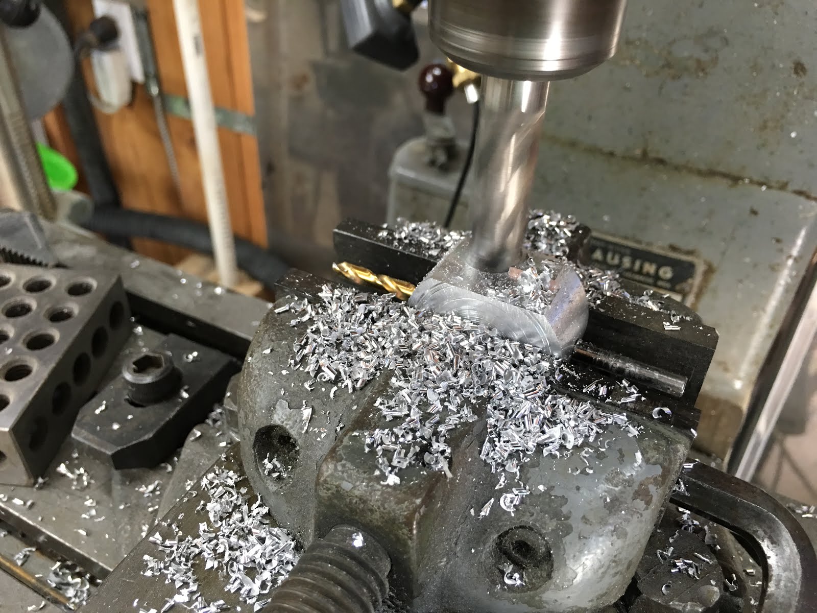
And then I used the mill to shave down the size, as they didn't need to be so dang big. Should cut down the weight a little bit. Used the bolt hole for alignment, although it really didn't matter.

Now almost completed. The right dimension to slide down in the step tube, Cut down to reduce the bulk a bit, and drilled for the bolt hole.
On trying one in, it was a pretty tight fit, which is what I want. The challenge is that proper placement is down the tube about 10".

So I tapped the side for a 1/4" thread, and did the same on a long piece of drill rod. As a result, I can carry it down the tube, and even rotate it around to the right orientation. Once in place, I can secure it with a temporary bolt and back out the drill rod. It worked fine.

Here is a picture of the access panel I fabricated in order to access the step bolt in the future. This is in the front of the baggage area. I had to notch the access plate so that the bolt could be removed if needed. It comes straight up and there was no other way to do it that I could see. But it worked fine.

This is the bushing, screwed onto the "insertion tool", and the step tube that it will go into. It is a snug fit, but can be wrangled around enough to get into place.

Step bushing inserted, before the tool has been unscrewed.

Now the step has been inserted from the outside of the fuselage. There is an inner brace that holds the inside end of the step. The steel fitting on the fuselage (powder coated white) was final drilled with the bushing/step lined up. Finally the bolt is dropped in, everything fits great and can be torqued tightly.
BTW, that is the comm antenna doubler just to the left. Ready to rivet that in place soon.

Not sure if one more view is necessary, but.....

And here is how the outside of the step looks, with the plane tilted over to work on. The step is a great feature, wish one was on the RV-6A of John's that I fly. However, during construction it is a shin-buster. Since I have access via the inspection plate, I will remove until final assembly.
Tuesday, April 19th
Fuselage and Wings have arrived!
My Quick-build wings and fuselage arrived a few weeks ago. They had a long journey from Oregon to the Phillipines, where they were assembled at an aircraft manufacturing plant. Then they were put on a boat back to Oregon again, where Vans Aircraft inspected them. Once they were "blessed" by Vans, they were put on a truck and shipped down to me.
I had a rolling cart made for each of them, and unloading and storage was fairly easy. The hard part was talking Julie out of some garage space for my wings for the time being.
Both assemblies are about 90% completed. They allow for me to do a lot of plumbing/wiring before I finally close them up. This is a big boost in my time-line and helps a bunch.
And I also just received from the FAA notice that I have successfully reserved......
N12CL!
Although reserved but not yet committed, I think it is an excellent N# for my aircraft. It rolls off the tongue pretty easy....November one, two, charlie, lima. I just need to keep it reserved until it would be time to register at the end of the build. Hmmmm.

Here is the fuselage, sitting in my shop. I began by removing the floorboards (where my drill is sitting in the photo). There were only temporary rivets placed, as I am required to remove them to rivet both halves of the fuselage together properly. (Please note FOX News on the TV, with nauseating political news).
Here are pics of the two halves clecoed together, ready for final drilling and assembly.....


And of course, it all has be taken apart and deburred, dimpled and countersunk. Putting everything back together again this weekend and hopefully throw in a few rivets.
